Continue to Site

Welcome to EDAboard.com

Welcome to our site! EDAboard.com is an international Electronics Discussion Forum focused on EDA software, circuits, schematics, books, theory, papers, asic, pld, 8051, DSP, Network, RF, Analog Design, PCB, Service Manuals... and a whole lot more! To participate you need to register. Registration is free. Click here to register now.

Creating a sigma Delta ADC model

Status
Not open for further replies.

dawson

Member level 1
Joined
Oct 13, 2012
Messages
34
Helped
1
Reputation
2
Reaction score
1
Trophy points
1,288
Activity points
1,537
Hi,
I need to generate a 1st order sigma delta ADC and run the simulation of the output. values can vary. I need a guide to use which software to allow me to perform the model simulation.
currently i've found out others using Matlab, Circuit maker, Labview. Which 1 is a better option and anyone have any similair examples for me to references.

Required urgent support thanks.
Dawson
 

Thanks. i've downloaded it but unable to run it maybe i'm very much new to matlab.. basically i wanted to construct a 1st order SD ADC. i have found the schematic. just that where can i find the models ..example i need integrator, comparator, 1 bit DAC as well as decimation models I'm currently stuck at that point. i'm also trying out circuit maker .. anyone can give me a first kick to how to start it??
 

you can use Verilog-A to model the adc. you just need to know the transfer functions and mathematical relationships of the components in the modulator
 

You can use cadence spectre for simulations. You can build the individual circuit models in spectre with transistor models. Ideal blocks from ahdl library can also be used.
 

hi guys, thanks.. any example? block diagram.jpg i need to design this out but not all model are in matlab.. i will have a sine wave maybe from -12V to 12V and i will need to display the output bit.. but how do i define no of bits??
 

the output of the comparator will be either 1 or -1 so it will be 1 bit output. But u can have more than one bit if the quantizer is flash type
 

or rather i need to contruct something like this website given

https://www.maximintegrated.com/app-notes/index.mvp/id/1870

my project supervisor suggest that i do simulation for the analog portion then after that do digital portion which is the LPF and decimation part.. after that try to intergated both design together to get the output .. i need to show that the SNR improvement. (he suggest labview or circuit maker)
but if i were to use matlab i can combine them together without integrating the analog part with the digital portion.

Im now lost... i'm not very familiar with any of these program. i've downloaded the matlab model but dont know how to use them..
 

first of all u need u understand the modulator portion. it consists of
1. Loop filter which is basically an integrator in discrete time ie z tranform so u need to know about z transfroms and then how to create a filter in z-domain
2. Quantizer which is basically is 1 bit comparator which can be implemented using sign block in Matlab Simulink
3. DAC which is again 1 bit in simple case
4. Clock which samples the input signal and the quantizer is also clocked with it

the output will be a bitstream of 1 and -1 then u can do decimation to get the high resolution output.

- - - Updated - - -

read this paper "Behavioral modeling of switched-capacitor sigma-delta modulators "

1. loop filter or integrator = integrator.jpg (correct me if i'm wrong)
2. quantizer where to get the model i cant find it in the matlab simulink block..
3. DAC - no idea..
4. clock is integrated into the comparator?
 

1. yes that is a delayed ideal integrator, it has to be multiplied with capacitor ratios C1/Cf
2. 1 bit quantizer can be implemented using a sign block in simulink
3. DAC is converting the 1 bit output into analog value which is either + Vref or -Vref ie if output bit is +1 then dac output is +Vref and so on.
4. the comparator consists of quantizer and d flip flop that samples the output of the quantizer. clock given to the d flip flop is the sampling clock.
 

lately i have tried using circuit maker to do component level of sigma delta adc.. but i am not able to get the output correctly.. anyone can help me out?

micro designer. for matlab the DAC how to design?
dawsoncircuitmaker.jpg

- - - Updated - - -

matlab simulation... am i doing correctly..??
dawson matlab.jpg
 

the integrator you are using a continuous time one so it means you have a ct sdm. overall the matlab model is fine. how is the progress now ?
 

OversamplingMfile.jpgFFT1.jpg

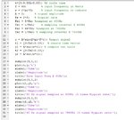
Hi i need help i've manage to create the oversampling of the original signal but how do i get the PSD using Matlab M file.. This is my source code

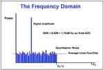
oversamplingM.jpg.. i need help how to make the sine wave into PSD to see the noise being spread out from 5*Fs to 64*Fs..

Thanks
Dawson
 

i'm going to start back from basic.. i should start with analog portion or digital part??? im now looking into the digital portion.. can give me a head start?
 

You do understand the basics? A Sigma-Delta A/D uses a integrator in a feedback loop (modulator) to generate a 1-bit data stream whose average value equals the analog input voltage (you can actually run it through a simple analog filter to recover the analog signal. The super audio CDs from Sony use that technique). This is converted to a multi-bit parallel word stream at a lower frequency by the digital filter, which averages the 1-bit values to generate the word values. The number of valid bits in the digital filter output and the word rate is determined by the oversample frequency for the highest analog input frequency by the 1-bit modulator and by the order of digital filtering used. These must be known before you can start the design. You can't do the design without specs first.
 

It is a easy one to build a First order sigma delta modulator using Simulink.FOr the Integrator you can either use a delay integrator like you did or Non-delayed one .For the Quantizer you need to either use a Quantizer block from simulink(search for quantizer) and the output from the quantizer can be directly subtracted from the input .the quantizer can also be implemented by the Zero-crossing/sign detector block.The oversampling ratio is what needed to be selected in such a way that you get the required SNR .By the way what is your Input frequency and what SNDR are you trying to achieve .
 

It is a easy one to build a First order sigma delta modulator using Simulink.FOr the Integrator you can either use a delay integrator like you did or Non-delayed one .For the Quantizer you need to either use a Quantizer block from simulink(search for quantizer) and the output from the quantizer can be directly subtracted from the input .the quantizer can also be implemented by the Zero-crossing/sign detector block.The oversampling ratio is what needed to be selected in such a way that you get the required SNR .By the way what is your Input frequency and what SNDR are you trying to achieve .

Hi naveensai.. sorry for late reply i was away for examination.

I have no specific specification for the ADC.

BTW this is my initial specification

• Type of modulator: First order delta-sigma modulator
• Input: Positive and negative rails of 5V and -5V
• Resolution: 12-bits of digital resolution
• Input frequency: 1kHz
• Clock frequency: 5MHz
• Sampling frequency: 60kHz (Nyquist rate of 30kHz)
• Filter: Finite Impulse Response (FIR) Low Pass filter (LPF)

from my previous simulation with simulink i cant generate out the Amp portion.. i only can do 1V, i think because i use the normal integrator block and also i use compare with zero .. how do i do if i have amplitude of 5 and -5V..

Thanks guys ..
 

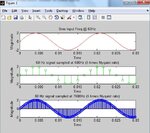
hi anyone around can help me with my digital portion.. i've been stuck for 2 week unable to get my decimation filter up .. need advice and guidance and examples if any of u have.. really appreciatedawsonadc.jpgdawsonwaveform.jpg

simulation stop time = 0.03
input sine signal = Amp= 12, Freq=2*pi*60
Clock period=1/7680 (oversampling of 64 times)
rate transition output sample time =1/7680

i've just add a FIR decimation block using dialog parameter coefficient
fir filter coefficient = fir1(35,0.015) <-- i dont understand this part so i just add random numbers
decimation factor = 8
<--- i tried change to decimation factor of 16 my waveform even more jagged.

end up i got the output(bottom waveform) is delayed by 90 degree as compare to the original sine wave(top waveform). what/how to remedy this?

how do i use multirate filter object (MFILT)??

In red are my queries. who can guide/teach or maybe show me some examples on how to make the filter
 
Last edited:

is my input frequency rate too low? my oversampling frequecy also too low. i saw examples mostly in oversample @ Mhz..
 

Status
Not open for further replies.

Similar threads

Part and Inventory Search

Welcome to EDABoard.com

Sponsor

Back
Top