Continue to Site

Welcome to EDAboard.com

Welcome to our site! EDAboard.com is an international Electronics Discussion Forum focused on EDA software, circuits, schematics, books, theory, papers, asic, pld, 8051, DSP, Network, RF, Analog Design, PCB, Service Manuals... and a whole lot more! To participate you need to register. Registration is free. Click here to register now.

Overshoot of clock signal on oscilloscope

Status
Not open for further replies.

PeterTr

Newbie level 6
Joined
Feb 7, 2012
Messages
11
Helped
0
Reputation
0
Reaction score
0
Trophy points
1,281
Activity points
1,376
Hello,

I was wondering what the explanation for the following observation is:

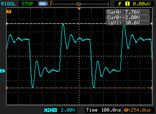
When looking with an oscilloscope at the clock signal that I generate with a microcontroller I do _not_ see an expected amplitude range of 0V to 5V but a large overshoot blow 0V and above 5V. See attached image. Are these amplitude real or just some sort of artefact due the interaction of the input stage of the oscilloscope with the steep transients ? If they are real, can they damage other components that are driven by this clock?

Thank you!
Peter


It's not the oscilloscope input stage but maybe the probe, typically the ground clip. It may be real as well, depending on the circuit. A CMOS IC, e.g. a µC will usually clamp the voltage 0.7 V below/above the supply rails. Seeing no clipping at all suggests that it's a measurement artefact.

Overshoots can damage sensitive components, particularly if they don't implement clamping diodes.
 
  • Like
Reactions: gasingh

    V

    Points: 2
    Helpful Answer Positive Rating

    gasingh

    Points: 2
    Helpful Answer Positive Rating
At a ~20MHz ring-note, this might be about local decoupling
"tanks". But ground clip positioning does matter. For higher
speed (edge rate) signals you now see differential probes
with very tight ground-prong spacings to the tip.
 

Are you using a 10:1 probe?

If so is the ground clip short and connected to a ground point close to the signal measuring point?
 

Thank you very much for all the answers!

As it turned out, the origin for the observed behaviour was the probe I used. It was a basic BNC cable with clips attached. Using the ( matching ) probes that came with the oscilloscope showed the expected waveform.
 

So you have learned something about oscilloscope probing...
 

for sure I learned something ... but why does it always has to be the hard way ... ;-)

By the way, I followed your earlier advice on using a differential amplifier with great success ... Thanks again!
https://www.edaboard.com/threads/240653/?#post1030233

- - - Updated - - -

for sure I learned something ... but why does it always has to be the hard way ... ;-)

By the way, I followed your earlier advice on using a differential amplifier with great success ... Thanks again!
https://www.edaboard.com/threads/240653/?#post1030233
 

Status
Not open for further replies.

Similar threads

Part and Inventory Search

Welcome to EDABoard.com

Sponsor

Back
Top