Continue to Site

Welcome to EDAboard.com

Welcome to our site! EDAboard.com is an international Electronics Discussion Forum focused on EDA software, circuits, schematics, books, theory, papers, asic, pld, 8051, DSP, Network, RF, Analog Design, PCB, Service Manuals... and a whole lot more! To participate you need to register. Registration is free. Click here to register now.

8 leds project problem

Status
Not open for further replies.

hesho90

Member level 4
Joined
Sep 3, 2012
Messages
78
Helped
0
Reputation
0
Reaction score
0
Trophy points
1,286
Location
egypt
Activity points
1,778
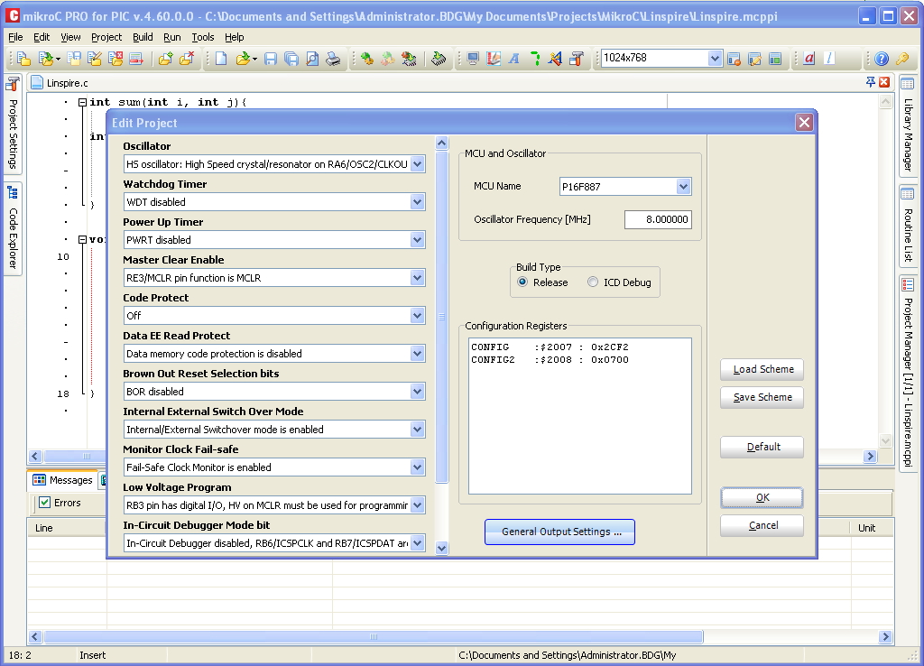
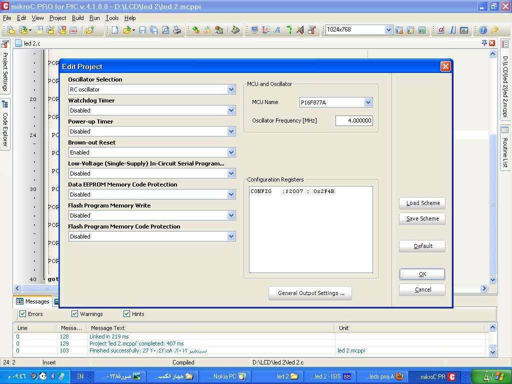
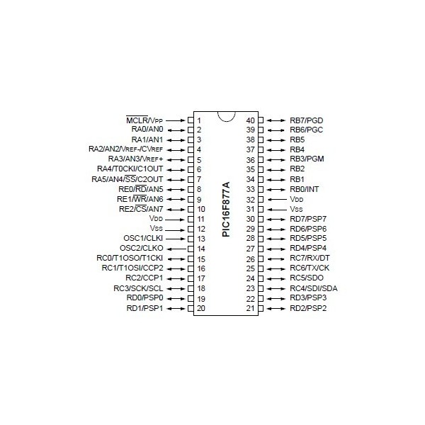
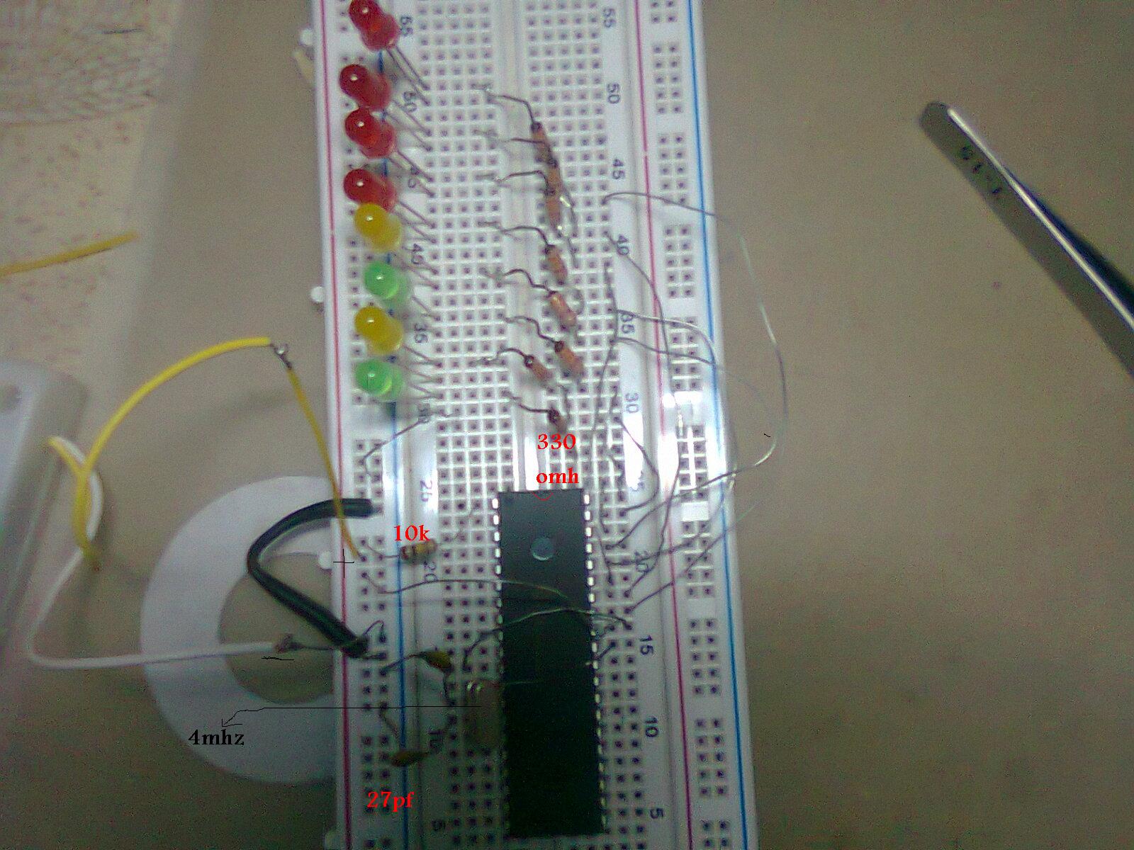
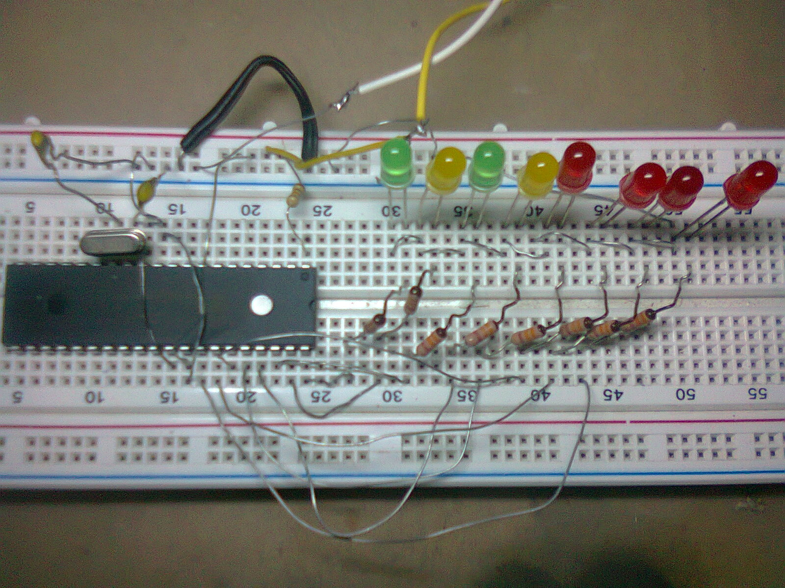
i got 8 leds and pic 16f877a

i made the code

Code:
void main() 
{TRISB=0; PORTB=0;

        Loop:

PORTB=0B00000001; delay_ms(500);

PORTB=0B00000011; delay_ms(500);

PORTB=0B00000111; delay_ms(500);

PORTB=0B00001111; delay_ms(500);

PORTB=0B00011111; delay_ms(500);

PORTB=0B00111111; delay_ms(500);

PORTB=0B01111111; delay_ms(500);

PORTB=0B11111111; delay_ms(500);

PORTB=0B00000000; delay_ms(500);

 PORTB=0B00011000; delay_ms(500);
 
 PORTB=0B00111100; delay_ms(500);
 
 PORTB=0B01111111; delay_ms(500);
 
 PORTB=0B00000000; delay_ms(500);
 
PORTB=0B11111111; delay_ms(500);

PORTB=0B00000000; delay_ms(500);

PORTB=0B11111111; delay_ms(500);

PORTB=0B11111111; delay_ms(500);

goto loop;}

led.JPG
 
Last edited by a moderator:

You dont say what your problem is .
Probably that the led at RB4 will not work as that output is open collector.
 
  • Like
Reactions: hesho90

    hesho90

    Points: 2
    Helpful Answer Positive Rating
they dont led up in the bread board
 

Make sure that the configuration bits are correct by specifying them at the source code or at the programmer.
In your schematic there is no crystal on the oscillator pins. It should be there in the real circuit.
There are other options other than a crystal to make the F877A work but what ever you use must be correctly set in the configuration bits.
Once you get it working check RB4 on the datasheet that led is not going to lit in your circuit.
 
  • Like
Reactions: hesho90

    hesho90

    Points: 2
    Helpful Answer Positive Rating
Are you using mikroC? Have you set the right clock frequency in real hardware and also in mikroC?
 
  • Like
Reactions: hesho90

    hesho90

    Points: 2
    Helpful Answer Positive Rating
As internetuser2k12 points out many of the MikroC library routines rely on the correct Oscillator Frequency (Fosc) being specified in the MikroC IDE.

All delay routines are among these which require the Oscillator Frequency be properly specified.

You can enter the Fosc in the menu item Project => Edit Project... dialog box.


You can also ensure the proper Configuration Register settings within the same dialog box as albert22 has pointed out.

Ensure you have disabled the watchdog timer, otherwise the PIC will continually reset instead of fully executing your code.

And disabled both Low Voltage Programming (LVP) and Debugging as these features utilize RB3, RB6 and RB7.

An alternative would be to move the LEDs to PORTD which does not share its pins with other peripheral modules or features.

I would also recommend utilizing an infinite loop (SuperLoop), rather than the use of a GOTO.

You might try the following:

Code:
void main() 
{
        TRISB=0; 
        PORTB=0;

        while(1)
        {
                PORTB++;
                delay_ms(500);
        }

}


BigDog
 
  • Like
Reactions: hesho90

    hesho90

    Points: 2
    Helpful Answer Positive Rating
i did chang the code didn t know what to chang but here is a phto of the circket on breadboard and the edit project


- - - Updated - - -

i did chang the code didn t know what to chang but here is a phto of the circket on breadboard and the edit project


Is your microcontroller powered up? (guessing PICs use the pin 20/40 convention, but it was hard to see if they were connected).
 
  • Like
Reactions: hesho90

    hesho90

    Points: 2
    Helpful Answer Positive Rating
yes i wierd pin 11 and 32 to power and pin 1 to
 

ok. I can't see that in your photos. You need to make sure the reset pin (whichever that one is) is also set to not reset (check the datasheet to
see if you need a resistor and capacitor on the reset pin or not. Also, put a 100nF decoupling capacitor across the microcontroller supply pins.
How are you powering up? From a battery? Is there a voltage regulator?
 
  • Like
Reactions: hesho90

    hesho90

    Points: 2
    Helpful Answer Positive Rating
Sorry. My fault RB4. Is not open Drain.
I see the connection to Vdd on pins 11 and 32.
But I dont see the required Vss on pins 12 and 31 to GND.
To make sure the pic is powered. check for +5 ( pins 11 and 32 ) referenced to pins 12 and 31. Do this placing the multimeter directly on the IC pins.
 
Last edited:
  • Like
Reactions: hesho90

    hesho90

    Points: 2
    Helpful Answer Positive Rating
i did chang the code didn t know what to chang but here is a phto of the circket on breadboard and the edit project

You need to change the Oscillator Selection of Configuration Register settings to XT or HS, it is current set to RC.

I would also advise you to upgrade to a more recent version, as the Background Debugging Selection of the Configuration Register Settings appears to be missing.

Background Debugging needs to be disabled.

BigDog
 
  • Like
Reactions: hesho90

    hesho90

    Points: 2
    Helpful Answer Positive Rating
there is no reset pin i think


the power is normel 4.5 v come from 3 1.5v battres


i have connected the 11/32 to power and 12/32 to ground and 13/14 to the xrtl 4mhz and connect bpth ofhet pin to 27pf and both of them to ground and the the (+) of the leds to 330omh and the other side to portb and and there(-) togther and the last one to the groun of the battery


- - - Updated - - -

what to chang in thin code

Code:
void main() 
{TRISB=0; PORTB=0;

        Loop:

PORTB=0B00000001; delay_ms(500);

PORTB=0B00000011; delay_ms(500);

PORTB=0B00000111; delay_ms(500);

PORTB=0B00001111; delay_ms(500);

PORTB=0B00011111; delay_ms(500);

PORTB=0B00111111; delay_ms(500);

PORTB=0B01111111; delay_ms(500);

PORTB=0B11111111; delay_ms(500);

PORTB=0B00000000; delay_ms(500);

 PORTB=0B00011000; delay_ms(500);
 
 PORTB=0B00111100; delay_ms(500);
 
 PORTB=0B01111111; delay_ms(500);
 
 PORTB=0B00000000; delay_ms(500);
 
PORTB=0B11111111; delay_ms(500);

PORTB=0B00000000; delay_ms(500);

PORTB=0B11111111; delay_ms(500);

PORTB=0B11111111; delay_ms(500);

goto loop;}
 
Last edited by a moderator:

What is the progress on your project?

Have you managed to blink the LEDs?

Ensure you use the CODE tags (#) button rather than QUOTE tag button as the CODE tags retain the proper formating.

Again, I would suggest avoiding the use of GOTOs in C code, its considered a bad habit and technique.

Try using a infinite loop (SuperLoop):

Code:
void main() 
{TRISB=0; PORTB=0;

        while(1)
        {

                PORTB=0B00000001; delay_ms(500);

                PORTB=0B00000011; delay_ms(500);

                PORTB=0B00000111; delay_ms(500);

                PORTB=0B00001111; delay_ms(500);

                PORTB=0B00011111; delay_ms(500);

                PORTB=0B00111111; delay_ms(500);

                PORTB=0B01111111; delay_ms(500);

                PORTB=0B11111111; delay_ms(500);

                PORTB=0B00000000; delay_ms(500);

                PORTB=0B00011000; delay_ms(500);
 
                PORTB=0B00111100; delay_ms(500);
 
                PORTB=0B01111111; delay_ms(500);
 
                PORTB=0B00000000; delay_ms(500);
 
                PORTB=0B11111111; delay_ms(500);

                PORTB=0B00000000; delay_ms(500);

                PORTB=0B11111111; delay_ms(500);

                PORTB=0B11111111; delay_ms(500);
        }
}

BigDog
 

thank you very match everyone it warked it make me happey

here is a video of it
 

Attachments

  • فيديو٠٠١٩.rar
    1.7 MB · Views: 48

Status
Not open for further replies.

Part and Inventory Search

Welcome to EDABoard.com

Sponsor

Back
Top