Continue to Site

Welcome to EDAboard.com

Welcome to our site! EDAboard.com is an international Electronics Discussion Forum focused on EDA software, circuits, schematics, books, theory, papers, asic, pld, 8051, DSP, Network, RF, Analog Design, PCB, Service Manuals... and a whole lot more! To participate you need to register. Registration is free. Click here to register now.

LM723 voltage regulator

Status
Not open for further replies.

gehan_s

Member level 3
Joined
Aug 31, 2012
Messages
62
Helped
3
Reputation
6
Reaction score
3
Trophy points
1,288
Location
Sri Lanka
Activity points
1,799
dear all,

i am trying to make a voltage regulator using LM723. i understand the voltage regulation part. what i need is the current limiting. i have designed a P1000294.JPGopamp circuit to limit the current. it works as follows. i add a series 1ohm resistor to the load and measure the voltage difference across it. then i amplify the output (with a gain of 3.3) of it and give it to a comparator which compares it with a reference value set by me. if the output of the in-amp is larger than the set value it will turn on the internal current limiting transistor. i have connected the emitter of that transistor to the output of the power supply via a 10ohm resistor (C) to prevent the output shorting with the error amplifier.
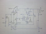
the maximum current i'm hoping to take out is 1.5A with a Vout max of 28V. the reason i added the 3.3 gain is because i want it to be converted to a digital value for displaying purposes. hence at maximum current my in-amp will give about 4.9V.

my questions are,

1. will this opamp circuit work? (specially because i am trying to measure very small difference voltages and will the in-amp withstand these high voltages at its +,- terminals)

2. do i need the 10ohm resistor at pin 3 OR is there a better way to do it ????

3. can i connect the in-amp output straight away to pin 2 via a resistor ad get rid of the LM358

4. is there a better way to do all of these things?????

i have added a picture of my design herewith

thanks in advance
 

Hi Gehan
s. i add a series 1ohm resistor to the load
One ohms resistor is unreasonable because it will increase voltage drop . you'd better to decrease it as low as 0.27 ohms or perhaps 0.1 ohms .
i have connected the emitter of that transistor to the output of the power supply via a 10ohm resistor (C) to prevent the output shorting with the error amplifier.
It is absolutely unreasonable . emitter should be connected to the ground ! how you expect to limit current in the arrangement that you have mentioned before ?!
2. do i need the 10ohm resistor at pin 3 OR is there a better way to do it ????
Pin 3 ? why ?
By the way , why you have connected your compensation capacitor like that ? it should be in your loop . a suggestion to remove comparator : use your current sensor in series with ground ! thus you won't need that comparator ! the op amp of current sampler can be used as it !
4. is there a better way to do all of these things?????
Of course there are many better ways available .
Best Wishes
Goldsmith
 

How low current do you want to limit to? Your using a AD622, <100uV Offset, so unless you need limit at 1mA, advise to decrease shunt resistor, or use a cheaper diff amp,
because it seems a waste there. The current sensor should be moved to the input before the series voltage reg IMO.
Can't see how your current limit is going to work with the emitter of the limit transistor tied to +V.....???
Also you are not limiting the base drive from the LM723 to the series pass transistor, you will most assuredly destroy the LM723 - study the specs carefully.


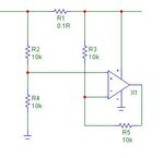
about your current sensor diff amp circuit. IMO you should hook it up like thus:I-Diffamp.jpg
But there are chips available to directly sense current like that, eg MAX4080
 
Last edited:

OK, have you looked at the data sheet for the 723. All that is needed for current limiting is a single series resistor connected between the CS and CL pins. Rs = Vs/Ilimit. If I recall correctly, Vs is about 0.75V. I have used this for current limiting and it works very well. The output Voltage is maintained for currents below the set limit because it is sensed after the series current sensing resistor. Again, look at the schematics on the data sheet.

If you want a digital readout of the current, you can still add an op amp across that current sensing resistor, but it is just for the readout, not part of the 723 circuit.
 

thank you all for replying so soon.

i connected the emitter to the O/P because something similar to that was in the data sheet current limiting section. if i connect pin 3 to ground wouldn't i be short circuiting the O/P of the error amplifier with ground (since there is no series resistor ). but i could use a series resistor with pin 3 and then ground it. will this help ??? i also had the following circuit in mind. in that it is using Q3 and R5 to set the maximum current. so even if the load is asking for more current the circuit simply won't give it. i also want this but i want to set different current limits. hence i have used the comparator method.

44444444444.JPG

you mentioned about better methods of doing this. can you please at least mention one of them (preferably low cost and easy to implement).
 

you mentioned about better methods of doing this. can you please at least mention one of them (preferably low cost and easy to implement).
Hi Gehan
Yes , an LDO ! a simple LDO ! with a simple current feed back and voltage to yield better quality and ability of variable current with more precision . if you are interested i can tell you more about it .
All the best
Goldsmith
 

thank you all for replying so soon.

i connected the emitter to the O/P because something similar to that was in the data sheet current limiting section. if i connect pin 3 to ground wouldn't i be short circuiting the O/P of the error amplifier with ground (since there is no series resistor ). but i could use a series resistor with pin 3 and then ground it. will this help ??? i also had the following circuit in mind. in that it is using Q3 and R5 to set the maximum current. so even if the load is asking for more current the circuit simply won't give it. i also want this but i want to set different current limits. hence i have used the comparator method.
yes, sorry, threw me off as to how to assure your comparator was going to switch on the current limit transistor, the base voltage needs to be higher than the emitter.
Looking at the internal circuit, current from the error amp is limited by a 1k resistor.
On the other hand current to the output is NOT limited,, so it is easily destroyed as I mentioned above. Hint:use a resistor

I was going to dish on selection of 723 too, for such an old design, about as old as the venerable 741. Surprisingly still in production going by the catalogs.
However it does have specified a very good precise and temp stable reference voltage included.......
 

I have to say something here. The 723 VR is a very old IC. At least 40 years old. It has been packaged in many different physical packages. Without going and looking, I believe I have one or two of them that I purchased in the 1960s that were in a metal can package. I have many in the DIP package. But it also comes in at least two more modern packages. And the PIN ASSIGNMENTS are NOT the same for every package. Since we do not know which package you are using, your saying "pin 3" is a worse than meaningless statement. It is a misleading statement. Pin 3 can be the CS or current sense pin (DIP package). Or it can be the CL or current limit pin (E20A). Or it can be the + or non inverting input (metal can). And, considering it's popularity, there are probably other pin-outs. It would be a lot better to use the In/Output NAMES as shown on the data sheet.

I have even seen ICs where just specifying the package type was still ambiguous. The chip manufacturers had made the same IC with different pin-outs in exactly the same package. Only the suffix of the part number told the story. And these were not OEM parts, they were in the data sheets.

I am guessing that you do not have the ancient metal can packages. So your "pin 3" is probably either the CS or CL connection. NEITHER of these should be grounded unless you are using a very exotic circuit. The 723 is very versatile so that may be the case, but if so, perhaps you should re-evaluate the use of that circuit. If all you want is a straight forward, positive Voltage regulator with current limiting, then look at the TI data sheet, page 8 and follow one of those circuits. They should do what you want, just fine.

https://www.ti.com/lit/ds/symlink/lm723.pdf

Paul A.


thank you all for replying so soon.

i connected the emitter to the O/P because something similar to that was in the data sheet current limiting section. if i connect pin 3 to ground wouldn't i be short circuiting the O/P of the error amplifier with ground (since there is no series resistor ). but i could use a series resistor with pin 3 and then ground it. will this help ??? i also had the following circuit in mind. in that it is using Q3 and R5 to set the maximum current. so even if the load is asking for more current the circuit simply won't give it. i also want this but i want to set different current limits. hence i have used the comparator method.

View attachment 80535

you mentioned about better methods of doing this. can you please at least mention one of them (preferably low cost and easy to implement).
 

one or two of them that I purchased in the 1960s
Hi Paul
1960 ? i think if at that time you had 20 years old (at least ) , now you are at least in 72 years old ! am i right ? :grin:
For the best variable PSU one other of my suggestions is a simple LM2576 ADJ + one simple op amp to control current in our desired rate .
Best Regards
Goldsmith
 

Polish up your math. 72 years old? Well, not for a few years yet.

I don't doubt that there are other chips and circuits that will make excellent supplies. But the OP was talking about a 723 circuit so I went with that. And, believe it or not, they do still work. And it does not need an additional op amp to provide current control. All he needs to do is read and follow the data sheet. In any case, 723 or another IC, it should be fairly easy to get the design he wants.
 

Two points won't work in the schematic according to post #1
- the voltage control will be limited according to the common mode range of the error amplifier (about 2V min.)
- in current limited operation, the output will be unstable without additional compensation

The original LM723 application circuits don't provide variable current limiting or a large voltage variation range. I assume, LM723 has been used for variable power supplies as well, but would need more external circuits then.
 

Polish up your math. 72 years old? Well, not for a few years yet.

I don't doubt that there are other chips and circuits that will make excellent supplies. But the OP was talking about a 723 circuit so I went with that. And, believe it or not, they do still work. And it does not need an additional op amp to provide current control. All he needs to do is read and follow the data sheet. In any case, 723 or another IC, it should be fairly easy to get the design he wants.
Hi Paul
At first about 723 i know it has an internally transistor but it is not enough to have variable current ( each good bench PSU needs variable current not just constant or just foldback ) as FvM said it would require more external components .
And another thing about your age !
Well, not for a few years yet.
what do you mean by that ? is that means that my calculations were not correct ? ha ha !
Respectfully
Goldsmith
 

µA723 was introduced by Fairchild in 1968. This is fact in the 60s, but not 1960.
Hi dear FvM
Oops . sorry , what a funny mistake of me ! so 2012-1968=44 44+20=64 !!! :grin:
Sincerely
Goldsmith
 

wow a lot of posts. well i have to say i wasn't expecting that many so many thanks to all of you. ok i will be straightforward with all of you. i just need a variable current limiting circuit for the lm723. my specs are 0-1.5A and >=2V to 28V
"pin 3" is probably either the CS or CL connection
i am using https://www.ti.com/lit/ds/symlink/lm723.pdf
 

The current limiting of the 723 is triggered by turning on an internal transistor and that should take 0.7 V across the sensing resistor. A high quality, 1K pot that is capable of a 0 Ohm setting with a small value resistor in series will provide a variable sensing resistor between the value of that small fixed resistor and the 1K maximum of the pot. I calculate 0.466 Ohms for the fixed resistor but if you buy one it will probably have to be 0.5 Ohms for a maximum current of 1.4 Amps. The 1K full value of the pot will limit the current to about 0.7 mA. I don't think any circuit, no matter how complex, will bring you down to a true value of 0 mA. The 1K value of the pot is not a problem because the Voltage sensing is attached at the load side of the sensing resistor and the 723 will bring it's output pin high enough to keep the Voltage at the load at the value that is set regardless of the current or resistor value. This should work for any output Voltage with no changes in the values of the fixed resistor or the pot. Remember, this thing will shut down when the Voltage across the sensing resistor reaches 0.7V so it will never be higher than that and the output of the chip or pass transistor will never be higher than the regulated Voltage + 0.7V. The pot could be calibrated for output current limit values.

As for the 2 to 28 Volt range, that may be more problematic. The 723 has two modes of operation, one for output Voltages below the reference Voltage of 7 Volts and another for output Voltages above that value. Again, you can see this from the data sheet: look for circuits labeled Low and High Voltage regulators. You would probably need to provide a switch to change circuit configurations and this switching would probably need to be done with power off (don't ask how I know that). If you need that wide of an adjustable Voltage range, then another VR chip may be a better choice.

In case you haven't noticed, the data sheet they you refer to shows three different versions of the chip.
 

Status
Not open for further replies.

Similar threads

Part and Inventory Search

Welcome to EDABoard.com

Sponsor

Back
Top