Continue to Site
Follow along with the video below to see how to install our site as a web app on your home screen.
Note: This feature may not be available in some browsers.
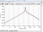
can any one help me to find gain bandwidth product of the bode plot i attached
It is probably a Multiple-Feedback-Bandpass-Filter circuit that has perfectly straight sides attenuating at 6dB per octave.
But notice that the right side begins bending down at about 2MHz, probably caused by the 3MHz gain-bandwidth product of the opamp.
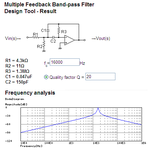
Of course it is a Multiple Feedback Bandpass filter with a high Q giving the sharp narrow peak and gradual single-order lowpass and gradual single-order highpass slopes for most of its response.No audioguru, I don't think that the response belongs to a second-order bandpass (why do you think of a MFB filter ?). Again: I think it's a circuit that differentiate (very poor phase margin as a typical property).
However, I think it's funny that we are guessing here - and the questioner (yadhu) does not tell us what kind of circuit he is investigating.
You mean, the transfer function looks similar.Of course it is a Multiple Feedback Bandpass filter with a high Q
Of course it is a Multiple Feedback Bandpass filter with a high Q giving the sharp narrow peak and gradual single-order lowpass and gradual single-order highpass slopes for most of its response.
The Multiple Feedback Bandpass Filter is the only filter I have seen with a sharp and narrow high-Q peak then gradual single-order slopes.
The high-Q of the circuit produces a peak that has an amplitude much higher than the opamp can do by itself.
I assume you are talking about filter gain. That's true e.g for an oscillator which achieves infinite gain. Similarly, the gain peaking of the present circuit can be explained by a near to zero phase margin.The high-Q of the circuit produces a peak that has an amplitude much higher than the opamp can do by itself.
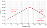
A simple single-order differentiator is not a active bandpass filter. If it is followed by a simple single-order (second-order?) integrator then the "peak" is not sharp and narrow.In fact, the shown transfer characteristic can be achieved by simple inverting differentiator, as already assumed by LvW in post #2.
A simple single-order differentiator is not a active bandpass filter. If it is followed by a simple single-order (second-order?) integrator then the "peak" is not sharp and narrow.
Thank you.The peaking is created by nearly zero phase margin of the differentiator circuit.
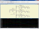
Me neither, you see why. Although the circuit is apparently acting as a high Q second order filter, I won't rely on the exact Q value, or at least circuit stability. You only need to add some capacitive load and make the circuit oscillating.I have never made a differentiator like that.
so it is a Multiple Feedback Bandpass filter circuit using only one capacitor and one resistor.
Me neither, you see why. Although the circuit is apparently acting as a high Q second order filter, I won't rely on the exact Q value, or at least circuit stability. You only need to add some capacitive load and make the circuit oscillating.
Assuming that the dominant pole in the OA is obtained with a feedback capacitor, then this is a sort of multiple feedback circuit (there are two nested loops), but not like the ones swown in posts #6 and #18.
Regards
Z