Continue to Site

Welcome to EDAboard.com

Welcome to our site! EDAboard.com is an international Electronics Discussion Forum focused on EDA software, circuits, schematics, books, theory, papers, asic, pld, 8051, DSP, Network, RF, Analog Design, PCB, Service Manuals... and a whole lot more! To participate you need to register. Registration is free. Click here to register now.

Query about MC34063A calculations

Status
Not open for further replies.

boylesg

Advanced Member level 4
Joined
Jul 15, 2012
Messages
1,023
Helped
5
Reputation
10
Reaction score
6
Trophy points
1,318
Location
Epping, Victoria, Australia
Activity points
11,697
This online calculator is pretty straight forward, but I was going to use the formulas in the data sheet to make my own calculator in a Excel spread sheet.:

**broken link removed**

In the online calulcator the value of the inductor (Lmin) is calculated.....simple enough.

But in the datasheet the value of a inductor is also calculated (Lmin) but there is also other inductor value at the top of each column for step up (170uH), step down (220uH) and inverting (90uH) calulcations.

What are these inductor values about and how do they relate to the formulas below them?
 

Your question about Excel is not clear. Can you upload a little more explanation on it?
 

The inductance values have been selected for application circuits shown on previous data sheet pages, please review. They should be related to the Lmin calculation.
 

The inductance values have been selected for application circuits shown on previous data sheet pages, please review. They should be related to the Lmin calculation.

That's what I don't understand exactly.

Should you always use and inductor of that value or should you use and inductor value that you calculate (Lmin)?
 

All inductance values have been selected for specific circuit parameters of these application circuits e.g. supply voltage, output current, switching frequency.
 

In the datasheet column headings it is clearly mentioned the Values are for if STEPPING DOWN circuit or STEPPING UP circuit or VOLTAGE INVERTING circuit.

snap.jpg
Hope it clarifies.
 

All inductance values have been selected for specific circuit parameters of these application circuits e.g. supply voltage, output current, switching frequency.
I am aware that they have provided example application circuits and that 170uH is the inductance value used in one such example.

But this table is for the formulas used to calculate the various component values in ANY application circuit. What has the 170uH inductance value got to do with other application circuits? For what purpose is it even listed in the table of generic forumals?
 

But this table is for the formulas used to calculate the various component values in ANY application circuit. What has the 170uH inductance value got to do with other application circuits? For what purpose is it even listed in the table of generic forumals?

This is an additional information provided just on same page. If you are not calculating for those circuits for which they are meant simply forget those values.
 

But this table is for the formulas used to calculate the various component values in ANY application circuit. What has the 170uH inductance value got to do with other application circuits? For what purpose is it even listed in the table of generic forumals?
I agree to the consideration.
 

This is an additional information provided just on same page. If you are not calculating for those circuits for which they are meant simply forget those values.

OK, that's what I needed to know for sure. Thanks.

- - - Updated - - -

I agree to the consideration.

That's the problem when technical workers write manuals. They make assumptions about what the reader already knows or will be able to deduce.

I know because I have been there and done that with a software manual I had to write one time. After the first attempt I had to step back and imagine I was not all that computer or MS Windows savy. Then the manual I wrote was more useful to the users/testers of the software.
 

I have wired up one of these circuits as per one of the online calculators:


Have used 100uH inductor but I don't know how accurate my Rsc is.

I used 3 x 0.22R resistors in parallel which my multimeter measures at 0.4R. Individually each measures about 0.6R.

But then I don't know how accurate my multimeter is at that low resistance level given the minimum range is 200R.

It basically works but it seems to continuously shoot up to about 33V and then slowy reduce to just above 19V.

What does this mean exactly? Something is not quite right some where.
Is it a result of sub optimal components or component values or have I got a connection wrong some where?

I was pretty careful wiring it up on my bread board however.

- - - Updated - - -

Actually I think I have answered my own question.

I was measuring the voltage without a load. So if I stick a 10k resistor across the output the voltage stabilises at about 33V. And if I plug 33V output into that calculator I get Rsc of 0.22R. So I can probably assume my multimeter is not to be trusted at low resistance values.

Tried a 0.56R resistor as this is the closest value to hand. Now the voltage repeatedly shoots up to 25V and decays down to about 19V....even with an output filter consisting of a 50uH inductor and a 10uF capacitor.

So what is causing this excessively large ripple?

Strange.....doesn't seem to be doing it now......perhaps there were a couple of component leads touching that should not have been.

Any way by switching R2 to 2 x 10k and R1 for 1.5k I can get the voltage output varying from 18V to 18.2V, with the additional output filter.

Anyway the bread board circuit seems to be working just fine now. Just need to modify my soldered version of the circuit accordingly.

Then I need to work on the negative version.

I noticed some where that you can also power a MC34063 boost converter with a negative voltage, by switching the GND and -12V rails.
 
Last edited:

I take it that the precise value of the sense resistor (Rsc) doesn't matter that much in these boost converter circuits, given that used a slightly higher value than the calculator specified but still adjusted the output voltage by changing R1 and R2?
 

déjà vu https://www.edaboard.com/threads/262768/ (posts #2 - #5)

I already used MC34063 as previously mentioned, but I won't suggest it as a "simple switcher", particularly not for a beginner.

A late comment about the table in #4. It can't be found in a recent MC34063A datasheet. I have Rev.6 (12 years old) and latest Rev23, both don't show the inductor values inside the calculation table. So we are apperently discussing a documentation wrongness of a last millenium datasheet.

https://www.onsemi.com/pub/Collateral/MC34063A-D.PDF
 
  • Like
Reactions: tpetar

    tpetar

    Points: 2
    Helpful Answer Positive Rating
déjà vu https://www.edaboard.com/threads/262768/ (posts #2 - #5)

I already used MC34063 as previously mentioned, but I won't suggest it as a "simple switcher", particularly not for a beginner.

A late comment about the table in #4. It can't be found in a recent MC34063A datasheet. I have Rev.6 (12 years old) and latest Rev23, both don't show the inductor values inside the calculation table. So we are apperently discussing a documentation wrongness of a last millenium datasheet.

https://www.onsemi.com/pub/Collateral/MC34063A-D.PDF

Thanks for that - its got a little more detail than the copy I have.

One page 9 in the photos of the completed circuit boards........

Those green components are radio frequency inductors I think I saw them called?

I would assume they are part of the additional filter on the output to further reduce the voltage ripple?

I have actually used another recoverd bobin style inductor in my additional filter. Is it likely to matter that much do you think?
 

Some application circuits have an additional 1 µH/100µF output filter. Its placed outside the feedback loop and shouldn't affect the device behaviour too much.

A problem that apparently shows in your tests is instability with without load. DeepOne suggested to provide 5 mA minimum load for stable operation.

I realised that not long after I posted it, so I added a 10k resistor as a load and measured the voltage across that.

At one stage the voltage was still rippling by a few volts but I have not been able to reproduce this since.

So there may have been some component leads touching, that shouldn't have been, or something. I am now getting a stable voltage of 18.1V to 18.2V with the additional output filter.
 

This is so annoying.

My bread board basic boost converter works beautifully and outputs a steady 18V.
It is essentially the same as this with different component values:
mc34063-step-up.gif


But I am damned if I can get the soldered version of the circuit to work using the same components.
I have replaced R1 and R2 with a 5k and 50k pot with the soldred circuit so that I can make adjustments

The only difference that I can find between the soldered and bread board circuits is as follows.....
Measuring the voltage across the diode when the circuit is powered shows that, in the soldered circuit, the voltage across the diode drops slowly from 12V to below 1V over the course of several seconds. Where as with the bread board circuit the voltage across the diode is pretty much instantaneously below 1V.

So it appears that, with the soldered circuit, the output capacitor is never discharging and not contibuting anything to the output voltage.
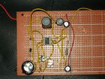
Don't know whether it is of any use but I have attached a photo of the circuit from the top.
Anyone spot anything wrong with it? Assuming that the soldering underneath is all good.BoostConverter.jpg

I cannot see any difference with the way I have connected the components together, other than the use of solder.
 
Last edited:

Status
Not open for further replies.

Similar threads

Part and Inventory Search

Welcome to EDABoard.com

Sponsor

Back
Top