Continue to Site

Welcome to EDAboard.com

Welcome to our site! EDAboard.com is an international Electronics Discussion Forum focused on EDA software, circuits, schematics, books, theory, papers, asic, pld, 8051, DSP, Network, RF, Analog Design, PCB, Service Manuals... and a whole lot more! To participate you need to register. Registration is free. Click here to register now.

How to recover the clock without using PLL?

Status
Not open for further replies.

iVenky

Advanced Member level 2
Joined
Jul 11, 2011
Messages
584
Helped
37
Reputation
76
Reaction score
35
Trophy points
1,318
Location
College Station, Texas
Activity points
6,124
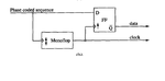
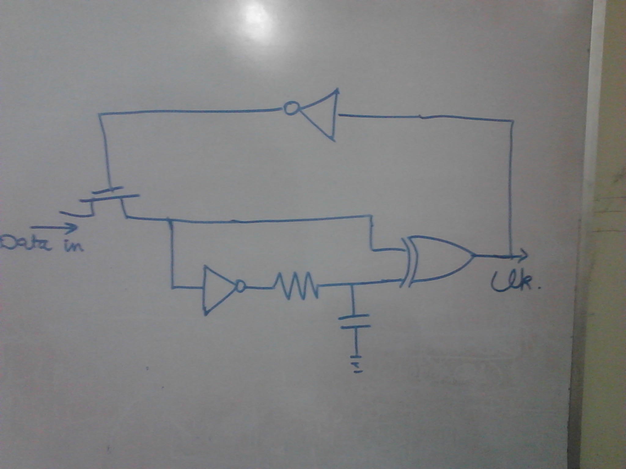
I am doing the IC design for data and clock recovery of Ask waveform of a Manchester coded data. I have no problem with the demodulation of Ask waveform to Manchester coded format. Now I want to recover the clock from the Manchester coded format and I am finding it really difficult. I have searched many IEEE papers. All those specify that I need a mono-flop (i.e. it will respond only for a certain period of time and if any trigger is there, a high/low voltage pulse will be the output.(during which it will not respond). ) I need the exact circuit to implement this operation. Note that there is no PLL involved.

How do you recover clock usually from a Manchester coded data as in passive RFID tags?


Thanks in advance.
 

Someone plz answer me this question.

Thanks a lot

- - - Updated - - -

I saw this circuit. But I don't know to design a mono-flop. What's the circuit for that?
 

Attachments

  • monoflop.png
    monoflop.png
    6.1 KB · Views: 191

Search for "hogge" or "alexander" phase detectors for clock and data recovery.
 

If you are referring to low frequency or 13.56 MHz RFID tags, they don't use PLLs or monoflop clock recovery circuits. Instead they are build as synchronous digital design clocked by the carrier frequency.
 

I don't know to design a mono-flop.
A mono-flop is a monostable multivibrator. Depending on the speed required, you may be able to use a 555 timer circuit.
 

The monoflop in post #2 seems to be dual-edge triggered. Surely different from a 555.

Apart from this point, it's not obvious how the design should work for basic manchester encoded data. Can you refer to a waveform diagram?
 

If you are referring to low frequency or 13.56 MHz RFID tags, they don't use PLLs or monoflop clock recovery circuits. Instead they are build as synchronous digital design clocked by the carrier frequency.

Hello Fvm. I would be really thankful if you could tell me(or provide me with some link) about the "synchronous digital design clocked by the carrier frequency".

Thanks a lot.
 

Unfortunately I don't have it. But considering the prerequisites of a tag design, it's an obvious way to make it. If you analyze the 13.56 MHz RFID standards, you'll notice that all timing specifications are based on carrier frequency periods.

The technical details of converting the AC voltage at the coil terminals to a digital clock may be different, you could even use a PLL. One requirement is to maintain a continuous clock source for modulation methods with 100 % ASK (ISO 14443 Type A), but the coil circuit Q should be basically sufficient for this purpose, when it's processed with a sensitive comparator.

One point against monoflop CDR methods is the fact, that RFID tags have to support different data rates. Another that it still has to work carrier synchronously in transmit mode, why should the design clock be switched between receive and transmit?
 

I am not actually designing an RFID tag. I just need to recover the clock and data and the data rate is not going to change. I am doing the receiver for ear implants. So there is only reception and I am not going to transmit anything from the receiver.

Thanks a lot.
 

I see. I guess that a carrier clocked design is still the most simple, however as you most likely have a battery supply and logic activities without RF on, there may be different aspects to consider.
 

One simple solution that is prone to edge noise is a an exclusive OR gate with a short RC delay on one side ( frequency doubler)
This then fires a second one shot that is non-retriggerable that is approx T * 0.75. The output is thus a steady frequency locking onto the one clock edge which is stable.

A synchronous demodulator or "matched filter" uses all the energy in the data to match a filter to the spectrum and thus integrates the data over the entire interval rather than differentiate the edges which is prone to edge glitches.

Implementation depends on need for power, speed, sensitivity and BER specs.
 

One simple solution that is prone to edge noise is a an exclusive OR gate with a short RC delay on one side ( frequency doubler)
This then fires a second one shot that is non-retriggerable that is approx T * 0.75. The output is thus a steady frequency locking onto the one clock edge which is stable.

I thought of this circuit before. I want know if this circuit will work or not. Do you have any idea what they actually do in RFID tags?

Thanks a lot.

- - - Updated - - -

I wish to use the mono flop. (I have attached the circuit in the beginning of this thread). I know to design a monoflop that would respond to either positive or negative edge. But the thing is that I don't know to design a mono flop that would respond to both positive and negative edges of the input. Do you have any idea?

Thanks a lot.
 

Examples of tag designs utilizing digital demodulators, with and without PLL processing of the carrier signal
 

Examples of tag designs utilizing digital demodulators, with and without PLL processing of the carrier signal

Hello FvM. I want the clock recovery for manchester coded data. I don't think they are for manchester coded data.

Thanks a lot.
 

I want the clock recovery for manchester coded data. I don't think they are for manchester coded data.
You are right, the popular 13.56 MHz RFID standards use different modulation methods for the PCD to PICC (reader to tag) direction, they have manchester encoding for the other way.

But I don't see a principle difference. For any modulation method, you need to synchronize bit and frame rate somehow. A digital demodulator, as implemented by the linked tag designs can easily demodulate manchester encoded data, if you want it to. Bit rate extraction for the modified miller coding used by ISO 14443 or 1-out-of-n with ISO 15693 is even slightly more difficult than with basic manchester coding.

I don't want to unsell the straightforward monoflop CDR method, but you have been asking about methods used in RFID tags.
 

I don't want to unsell the straightforward monoflop CDR method, but you have been asking about methods used in RFID tags.

I would be really happy if you could tell me about the monoflop. I want the monoflop to trigger on both positive and negative edges. How to do that?

Thanks a lot.
 

re-read my post #11 which defines how to do it. If Exclusive OR gate is fast enough, it will produce a pulse from each edge. ECL is best for symmetrical delays.
 
  • Like
Reactions: FvM

    FvM

    Points: 2
    Helpful Answer Positive Rating
re-read my post #11 which defines how to do it. If Exclusive OR gate is fast enough, it will produce a pulse from each edge. ECL is best for symmetrical delays.

I know to design a monoflop that would respond to positive edge but how to design a monoflop that would respond to both positive and negative edges?

Thanks a lot.
 

NAND gate with RC delay and inverter on one side detects one edge.. Using XOR gate detects both edge with delay time on one side.

Thanks a lot. Just tell me if this circuit is correct


Basically it should not respond to the edges between two same bits (either edge between 00 or 11). In order to ensure that I have to make sure that the transmission gate is off during that time.

So you mean the RC time constant should be larger than half period but smaller than full period of the clock?
 

Status
Not open for further replies.

Part and Inventory Search

Welcome to EDABoard.com

Sponsor

Back
Top