Continue to Site

Welcome to EDAboard.com

Welcome to our site! EDAboard.com is an international Electronics Discussion Forum focused on EDA software, circuits, schematics, books, theory, papers, asic, pld, 8051, DSP, Network, RF, Analog Design, PCB, Service Manuals... and a whole lot more! To participate you need to register. Registration is free. Click here to register now.

HELP - Full Bridge Inverter with IGBT and IR2110

Status
Not open for further replies.

Nysix

Junior Member level 2
Joined
Jun 9, 2012
Messages
20
Helped
3
Reputation
6
Reaction score
3
Trophy points
1,283
Activity points
1,435
Hi all,

Firstly, I'm new in this forum ;-) I don't speak english very well... Sorry in advance :-(

I need to design a full bridge inverter using IR2110 and IGBT (IRG4BC30) to vary the AC motor (150W) velocity. The switching will be

and I'll make it using a PIC16F877A.

I'm rectifying the line voltage (60 Hz, 180 V peak voltage) using a full bridge rectifier (MUR460 diodes). I have tested all schemes that I found, but I can't put them to work... I'm using the ISIS to simulate the circuit, but it don't work... I really need help to make this work. Anybody have a example or a tested scheme?

Other doubt, IR2110 and IR2112, for my purpose, are equivalents?

Thanks :)
 

You should state the exact problems you're facing.

I'm using the ISIS to simulate the circuit, but it don't work

Do you mean that nothing happens?

IR2110 and IR2112 are okay for your application. If you have them at hand, there's no need to use any equivalent. What you must ensure, though, is that you have configured the said drivers properly.
 
you are right Nysix,i simulate some Hex code using ISIS (Proteus) and it works but anytime i try to simulate using op-amps and other component it wont work,so i decide to used multism and it works fine.
 

Hi Tahmid and kabiru. Thanks for your replies. I appreciated :)

Tahmid, when I simulate the circuit in ISIS, the follow warning message appears:
[SPICE] TRAN: Timestep too small; timestep = 6.20658e-011 : trouble with node #00005.

I'm using the ISIS not long ago, I don't know if is possible solve this problem.
The circuit is:
circuito2.jpg

I don't know if I'm making a mistake. I'll use IR2110, but I not found it in the ISIS, then I'm using 2112.
__ EDIT _________________________________________________________

Hi all,

I finally got it to put my inversor's simulation to work :grin:
Using a +12V to the inversor, I got a rectangular waveform. But using a +180V voltage, I found the waveform showed in attachment. I think that the problem is the bootstrap capacitor. Unfortunately, I'll to use +180V. Someone knows a formula to calculate the bootstrap capacitor? I didn't found it in component's datasheet :sad:

Well, the waveform obtained in simulation should cross zero, not? :???:

teste.jpg
 
Last edited:

For the bootstrap diodes, use ultrafast diodes (like UF400X - you can use UF4004 in ISIS). Can you upload the Proteus file (*.DSN)? Then, I can take a look.

You can do a few things to speed up the simulation. Remove the AC alternator, bridge rectifier and capacitor, and just place a DC voltage instead.
 
  • Like
Reactions: Nysix

    Nysix

    Points: 2
    Helpful Answer Positive Rating
Hi Tahmid,

I removed all that you said and I changed the capacitor value to 330uF. Works great now :D
I noticed that the inverter's output contains a DC level. How I can remove it?

waveform.jpg
 

Connect a non-polar high voltage capacitor at the output - 1uF 250V/400V will do.

Which DC level are you referring to? That the output doesn't go all the way completely to zero (as it seems in the image)?
 

Hi Tahmid,

In image, I connected the probe in wrong place. The inversor works great now. Very very thank you for your help :D
I'll continue the project, but I need study PIC for make it :)
 

hi guys me also working on a power supply. i used the same circuit of Nysix but i am getting square wave at the output can anyone tell me what is the problem??? also i want to use irf840 but with them i got nothing at output..?? help please.
 

Hi malik_zohaib,

I think that the waveform in output depends of switching method.
 

i am using 60hz with 50% duty cycle. and what is your technique???
 

The output waveform depends on the drive signal. If you drive with 60Hz frequency and 50% duty cycle, you will get a full square wave at the output.

To get quasi-sine, drive with the same frequency but reduce the duty cycle to 40% to 45%. This would give you a quasi sine output.

To get sine wave, you need to drive with sinusoidal pulse width modulation with duty cycle continuously varying according to the steps required to make a sine wave.

Hope this helps.
Tahmid.
 

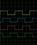
hi me using these gate signals.input.jpg
and my output without load is look like output.jpg
and with resistive load out.png

can you explain what kind of wave that is???
thanks.
 

The drive signal seems a bit odd. Why does one signal overlap with the next? This shows that the two waves aren't completely out of phase.

How are the signals obtained? Are you using a microcontroller? Can you upload the Proteus (*.DSN) file?
 

Before making other comments, I would like to ask a few questions:

1) What are you using to generate the 50Hz pulse? In the simulation, you use the signal generator but what do you intend to use in practice?
2) What kind of output do you desire/require?
3) What kind of output do you expect?
4) Is the 60 degree delay used to obtain a quasi-sine output?
 

1)i will use ucontroller.
2)quasi-sine or sine if possible.
3)from above circuit i expected quasi-sine.
3)yes

actually i tried many times to make inverter but never able to do that.
Regards.
 

Status
Not open for further replies.

Part and Inventory Search

Welcome to EDABoard.com

Sponsor

Back
Top