Continue to Site

Welcome to EDAboard.com

Welcome to our site! EDAboard.com is an international Electronics Discussion Forum focused on EDA software, circuits, schematics, books, theory, papers, asic, pld, 8051, DSP, Network, RF, Analog Design, PCB, Service Manuals... and a whole lot more! To participate you need to register. Registration is free. Click here to register now.

Help needed in Bandpass Microstrip filters. Using Ansoft Designer and HFSS

Status
Not open for further replies.

jaishankar

Junior Member level 2
Joined
Feb 9, 2012
Messages
21
Helped
0
Reputation
0
Reaction score
0
Trophy points
1,281
Activity points
1,480
xxasdfasdfasdf

xxasdfasdf asdfasdfsdf
 
Last edited:

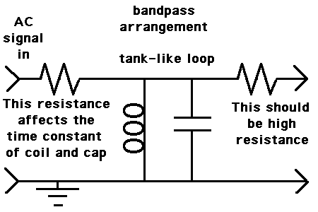
If you are talking about a tank-like loop used for bandpass (as in the schematic below)...

58_1335601124.gif


The capacitor comes into play by diverting high frequencies. The coil acts by diverting lows.

You will get some resonating action near the center frequency.

The input resistance will be a factor in determining what values you use for coil and capacitor.

For instance, if you use a 1pF capacitor, then a few ohms will yield a time constant suitable for the gigahertz range.

You can change the bandwidth by making the rolloff curves overlap to a greater or lesser extent. Shift the capacitor rolloff curve upward or downward by changing capacitor value or resistor value. In a similar manner you can shift the coil rolloff curve upward or downward. Always you must keep track of how you are altering the center frequency.

Changing the input resistor value will alter all time constants.

By making the outgoing resistance substantially higher than the input resistance, you reduce its ability to throw off the filter response.

---------- Post added at 03:26 ---------- Previous post was at 03:21 ----------

The simple filter shown above will not give you as sharp attenuation as your specs require.

The concepts above can be adapted to whatever type of filter you are using.

---------- Post added at 03:45 ---------- Previous post was at 03:26 ----------

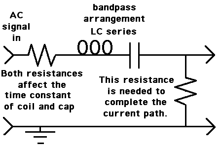
In case you are using an LC series bandpass, per diagram...

61_1335602656.gif


For this arrangement the output (rightmost) resistor needs to be low enough to allow some current flow.

A very high resistance will prevent the springy action which you want to occur at the bandpass frequency.
 

Hello,
i'm designing a microstrip band-pass filter. using ansoft designer and hfss

spec:

8GHz is the centerfrequency, 200MHz bandwidth (return loss should be >20dB in passband). and I need a attenuation of 40dB at +50MHz from pass band. Can someone help me out?
I am not able to get the attenuation immediately after the passband. Is there a way for it? i tried maximally flat and chebyshev..
(any suggestion is welcome..)

Thank you.

Hi jaishankar... super post da machi :p ennada namba specs maadiriye irukku nu paatha.. adha post pannathu nee :p lol
 

Status
Not open for further replies.

Similar threads

Part and Inventory Search

Welcome to EDABoard.com

Sponsor

Back
Top