Continue to Site

Welcome to EDAboard.com

Welcome to our site! EDAboard.com is an international Electronics Discussion Forum focused on EDA software, circuits, schematics, books, theory, papers, asic, pld, 8051, DSP, Network, RF, Analog Design, PCB, Service Manuals... and a whole lot more! To participate you need to register. Registration is free. Click here to register now.

adc0804 with 89s52, can't understand the code.

Status
Not open for further replies.

gonzalezteins

Newbie level 3
Joined
Apr 25, 2012
Messages
3
Helped
0
Reputation
0
Reaction score
0
Trophy points
1,281
Activity points
1,345
Dear all,

I am working ona project where i sense temp using PT-100, voltage comparator conditions the voltage to be between cmos limits. Following this adc 0804 converts A to D, and feeds to the micro-controller. the following is the cade, working fine! but i cannot understand a particular part:


Code C - [expand]
1
2
3
4
5
6
7
8
9
10
11
12
13
14
15
16
17
18
19
20
21
22
23
24
25
26
27
28
29
30
31
32
33
34
35
36
37
38
39
40
41
42
43
44
45
46
47
48
49
50
51
52
53
54
55
56
57
58
59
60
61
62
63
64
65
66
67
68
69
70
71
72
73
74
75
76
77
78
79
80
81
82
83
84
85
86
87
88
89
90
91
92
93
94
95
96
97
98
99
100
101
102
103
104
105
106
107
108
109
110
111
112
113
114
115
116
117
118
119
120
121
122
123
124
125
126
127
128
129
130
131
132
133
134
135
136
137
138
139
140
141
142
143
144
145
146
147
148
149
150
151
152
153
154
155
156
157
158
159
160
161
162
163
164
165
166
167
168
169
170
171
172
173
174
175
176
177
178
179
180
181
182
183
184
185
186
187
188
189
190
191
192
193
194
195
196
197
198
199
200
201
202
203
204
205
206
207
208
209
210
211
212
213
214
215
216
217
218
219
220
221
222
223
224
225
226
227
228
229
230
231
232
233
234
235
236
237
238
239
240
241
242
243
244
245
246
247
248
249
250
251
252
253
254
255
256
257
258
259
260
261
262
263
264
265
266
267
268
269
270
271
272
273
274
275
276
277
278
279
280
281
282
283
284
#include <At89x52.h>
#include "lcd.h"
#include "keypad.h"
#include "delay.h"
//=================================================================
=
#define adc_port P2                  //ADC Port
#define rd P0_6                     //Read signal
#define wr P0_5                 //Write signal
#define cs P0_7                 //Chip Select
#define intr P0_4                   //INTR signal
//=================================================================
 
#define RELAY P0_3
#define UNDERTEMP P0_0
#define OVERTEMP P0_1
//=================================================================
 
#define TEMP_LOW_LIMIT 0x00
#define TEMP_HIGH_LIMIT 0x01
//=================================================================
 
void conv();                    //Start of conversion function
void read();                     //Read ADC function
void delay1(unsigned int a);
void delay_100us(unsigned int a);       //0.1 ms
unsigned int enter_val(unsigned char mode);
int key_get(void);
 
//=================================================================
 
unsigned char adc_val;
unsigned int display_number=0;
//=================================================================
 
//Main function
 
void main()
{
unsigned long temp1,temp2;
unsigned long a1;
unsigned int low_limit,high_limit,high_alarm_limit;
float c,d,e,f,b,a,g,h;
 
P0=0x00;
P1=0xFF;
P2=0xFF;
RELAY=1 ;                           // relay off
UNDERTEMP=0;                        //0=sound off
OVERTEMP=0;                         //1=sound OFF
LCD_INIT();
LCD_CLEAR();
LCD_STRING("TEMP CONTROLLED");
LCD_CMD(PUTLINE2);
LCD_STRING(" FAN ");
delay_100us(10000);
delay_100us(10000);
delay_100us(10000);
delay_100us(10000);
LCD_CLEAR();
LCD_STRING("CURRENT TEMP");
high_alarm_limit = 130;
high_limit=120;
 
while(1)                //Forever loop
{
LCD_CMD(PUTLINE2);
conv();                                 //Start conversion
read();                                     //Read ADC
a=5*adc_val;
b=a/255;
 
//can't understand from here
[B][I]c= 8.4375 + b;
d= c*1500;
e = 149-c;
f = d/e;
g= (f-100);                                 //stright line equation
h =g/0.22; 
h=h+10;[/I][/B]
//can't understand till here
LCD_DisplayNum(h,3);
LCD_STRING(" DEG C");
delay1(10);
 
if(key_get()!=0)
{
switch(key)
{
case mode_key:
LCD_CLEAR();
LCD_STRING("
TEMP LIMIT SET ");
LCD_CMD(PUTLINE2);
LCD_STRING("MODE ");
delay_100us(20000);
delay_100us(20000);
LCD_CLEAR();
LCD_STRING("TEMP LOW LIMIT?");
LCD_CMD(PUTLINE2);
low_limit = enter_val(TEMP_LOW_LIMIT);
LCD_CLEAR();
LCD_STRING("TEMP HIGH LIMIT?");
LCD_CMD(PUTLINE2);
high_limit = enter_val(TEMP_HIGH_LIMIT);
LCD_CLEAR();
LCD_STRING("Low Limit:");
LCD_DisplayNum(low_limit,3);
delay_100us(10000);
delay_100us(10000);
delay_100us(10000);
delay_100us(10000);
LCD_CLEAR();
LCD_STRING("High Limit:");
LCD_DisplayNum(high_limit,3);
delay_100us(10000);
delay_100us(10000);
delay_100us(10000);
delay_100us(10000);
LCD_CLEAR();
LCD_STRING("CURRENT TEMP");
break;
break;
 
case start_key:
LCD_CLEAR();
LCD_STRING("Low Limit:");
LCD_DisplayNum(low_limit,3);
delay_100us(10000);
delay_100us(10000);
delay_100us(10000);
delay_100us(10000);
LCD_CLEAR();
LCD_STRING("High Limit:");
LCD_DisplayNum(high_limit,3);
delay_100us(10000);
delay_100us(10000);
delay_100us(10000);
delay_100us(10000);
LCD_CLEAR();
LCD_STRING("CURRENT TEMP");
OVERTEMP=0;
break;
}
}
 
 
if(h >=high_limit)
{
RELAY=0;//off
{
if(h >=high_alarm_limit)
UNDERTEMP=1;                            //OFF
OVERTEMP=1;                         //ON
}
}
 
else if(h <=low_limit)
{
RELAY=1;                                //OFF
UNDERTEMP=0;                            //ON
OVERTEMP=0;                         //OFF
}
}
}
 
// Function for A-D conversion
void conv()
{
cs = 0;                              //Make CS low
wr = 0;                             //Make WR low
wr = 1;                             //Make WR high
cs = 1;                                 //Make CS high
while(intr);                             //Wait for INTR to go low
}
 
//Function to read digital values to 89S52
 
void read()
{
cs = 0;                             //Make CS low
rd = 0;                             //Make RD low
adc_val = adc_port;                     //Read ADC port
rd = 1;                          //Make RD high
cs = 1;                         //Make CS high
}
 
//Delay function
 
void delay1(unsigned int a)
{
unsigned int b;
for(;a>0;a--)
{
for(b=0;b<1000;b++)
{
a--;
a++;
}
}
}
 
//Function for setting values of the upper and lower limit using up and down keys.
 
unsigned int enter_val(unsigned char mode)
{
unsigned int start_num=0;
unsigned int end_num;
unsigned int return_value;
bit num_complete=0;
 
if(mode==TEMP_LOW_LIMIT)
end_num=500;
 
if(mode==TEMP_HIGH_LIMIT)
end_num=500;
 
display_number=0;
LCD_DisplayNum(display_number,3);
 
while(num_complete==0)
{
while(key_get()==0);
switch(key)
{
 
case start_key:
num_complete=1;
return_value=display_number;
break;
 
case up_key:
if(display_number==end_num)display_number=0;
else displ ay_number = display_number +5 ;
LCD_CMD(PUTLINE2);
LCD_DisplayNum(display_number,3);
break;
 
case down_key:
if(display_number==start_num)display_number=end_num;
else display_number = display_number - 5;
LCD_CMD(PUTLINE2);
LCD_DisplayNum(display_number,3);
break;
 
case mode_key:
return 100;
break;
}
}
return return_value;
}
 
//Function to check which key is pressed out of the 4 at a given point of time.
 
int key_get(void)
{
if(start==0)
{
key=start_key;
do{delay_100us(100);}while(start==0);
delay_100us(500);                               //return key
}
else if(mode==0)
{
key=mode_key;
do{delay_100us(100);}while(mode==0);
delay_100us(500);                               //return key;
}
else if(up==0)
{
key=up_key;
do{delay_100us(100);}while(up==0);
delay_100us(500);                               //return key;
}
else if(down==0)
{
key=down_key;
do{delay_100us(100);}while(down==0);
delay_100us(500);                       //return key;
}
else key=0;                         //return 0
return key;
}


---------- Post added at 18:07 ---------- Previous post was at 18:06 ----------

it is kinda urgent, will be immensely grateful to you for your help :) thanks!

---------- Post added at 18:14 ---------- Previous post was at 18:07 ----------

Rt = R0 * (1 + A* t )
A = 3.9083 X 10 ^-3


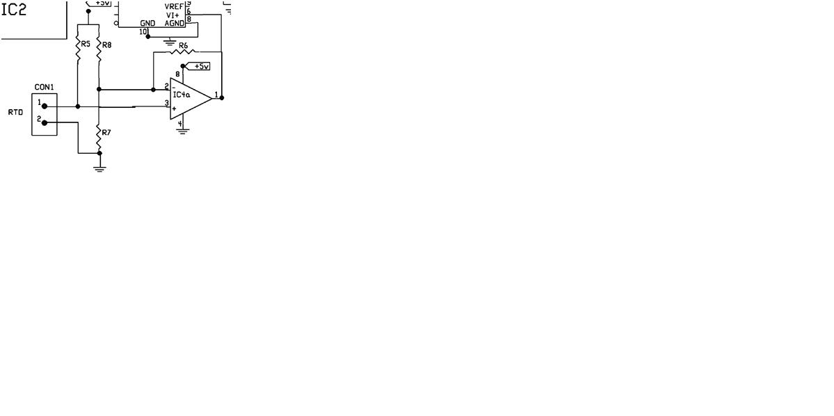
r5, r8, r6 are 2700Ω and r7 is 100Ω
 

This code implements (some kind of) interpolation/value adjust:

a=5*adc_val;
b=a/255;
c= 8.4375 + b;
d= c*1500;
e = 149-c;
f = d/e;
g= (f-100); //stright line equation
h =g/0.22;
h=h+10;

I assume you get the value of the temp sensor in "adc_val".

After the execution of this piece of code you get the temperature value from:

\[h=\frac{(\frac{(8,4375+\frac{5}{255}*AdcVal)*1500}{149-(8,4375+\frac{5}{255}*AdcVal)*1500}-100)}{0,22}+10\]

This is used when you get the value of a sensor (Voltage in CON1) through a particular circuit (Op Amp) and you need the value of the sensed variable (Temp).

What you get from the sensor is a voltage, after that you amplify/adapt the voltage to ones that the ADC can manage, and after that you do the ADC conversion. If you need the temperature, you have to use an ecuation to get the original temperature after these modifications.

You must include in the ecuation:
Gain of the circuit used to adapt/get the sensor value
Ecuation from the sensor datasheet that transforms, for example, temp to voltage.

Best regards.
 
Dear diego,
that is what i had assumed, but working backwards manually doens't match properly.
for example :
at 100 deg C, the resistance of the PT-100 is 138.4ohm, and working backwards using that equation it give about 150+ ohms.

Are you aware how to manually convert the ADC 0804 o/p to voltage? I am asking manually, so that i can cross check this.

Te mando Saludos,
Shr
 

Dear diego,
that is what i had assumed, but working backwards manually doens't match properly.
for example :
at 100 deg C, the resistance of the PT-100 is 138.4ohm, and working backwards using that equation it give about 150+ ohms.

Just suppositions..

As you should know, the variation of the resistance in an RTD is not linear with temperature... The guy that coded that application may have use a linearizion of the RTD curve so that he can have a lower error in that temp zone, with lightweight calculations ..

Or he can even be doing self-heating correction calculations...
 

It is not very clear, but it seems the VREF/2 pin in the ADC is left unconnected, so according the datasheet, the ADC value goes from 0 (0h) to 5V (FFh).

This is why the code first do:
a=5*adc_val;
b=a/255;
(Now I realize that this is the part of the code you actually understands)

The rest of the code, as mgate (and myself) says, depends on the analog circuit and sensor used.

Looking at the analog part of the circuit (and making some calculus) you get: \[V_O=\frac{R_{PTC}}{R_{PTC}+R_{5}}*144,99\], and as \[{R_5}\gg{R_{PTC}}\] you finally get \[{V_O}\approx{\frac{R_{PTC}}{R_{5}}*144,99}\approx{R_{PTC}*0,053}\]

(Actually it is: \[V_O=V_{CC}*(\frac{R_{PTC}}{R_{PTC}+R_{5}})*(1+R_{6}(\frac{1}{R_{7}}+\frac{1}{R_{8}})-\frac{V_{CC}}{R_8})\]. The above equation is what you get if you replace most of the resistors with their values.)

This doesn't make sense to me, i mean, the final equation must include some sort of compensation of the sensor.

Best Regards
 

Just suppositions..

As you should know, the variation of the resistance in an RTD is not linear with temperature... The guy that coded that application may have use a linearizion of the RTD curve so that he can have a lower error in that temp zone, with lightweight calculations ..

Or he can even be doing self-heating correction calculations...


I will check :)

---------- Post added at 01:39 ---------- Previous post was at 01:37 ----------

It is not very clear, but it seems the VREF/2 pin in the ADC is left unconnected, so according the datasheet, the ADC value goes from 0 (0h) to 5V (FFh).

This is why the code first do:
a=5*adc_val;
b=a/255;
(Now I realize that this is the part of the code you actually understands)

The rest of the code, as mgate (and myself) says, depends on the analog circuit and sensor used.

Looking at the analog part of the circuit (and making some calculus) you get: \[V_O=\frac{R_{PTC}}{R_{PTC}+R_{5}}*144,99\], and as \[{R_5}\gg{R_{PTC}}\] you finally get \[{V_O}\approx{\frac{R_{PTC}}{R_{5}}*144,99}\approx{R_{PTC}*0,053}\]

(Actually it is: \[V_O=V_{CC}*(\frac{R_{PTC}}{R_{PTC}+R_{5}})*(1+R_{6}(\frac{1}{R_{7}}+\frac{1}{R_{8}})-\frac{V_{CC}}{R_8})\]. The above equation is what you get if you replace most of the resistors with their values.)

This doesn't make sense to me, i mean, the final equation must include some sort of compensation of the sensor.

Best Regards


Diego,
I did'nt understand how so many equations emerged? you worked backwards? is it?
 

Consider your wheatstone bridge:
48_1335397981.jpg


with:

\[R_2=2700\Omega\]

\[R_1 = R_0 = 100\Omega\]


\[A = 3.9083 \times {10}^{-3}\]

\[(R_1 + \Delta{} R) = R_R_T_D = R_0 \times (1 + A \times{} t ) = R_0 + (R_0 \times{] A \times{} t) = R_1 + (R_1 \times{} A \times{} t)\]

so,
\[\Delta{}R = R_1 \times{} A \times{} t\]

\[V_A = \frac{(R_1 + \Delta{}R)}{(R_1 + \Delta{}R) + R_2 } \times{}V_S\]


\[V_B = \frac{(V_S + V_O)} {(2 + R_2/R_1)}\]

Consider the amp op ...
\[V_O = (V_A - V_B) \times{A_O_L}\]

\[V_O = \frac{V_A - \frac{V_S}{(2 + R_2/R_1)}}{\frac{1}{A_O_L} + \frac{1}{(2 + R_2/R_1)}}\]

\[V_O = \frac{\frac{(R_1 + \Delta{}R)}{(R_1 + \Delta{}R) + R_2 } - \frac{1}{(2 + R_2/R_1)}}{\frac{1}{A_O_L} + \frac{1}{(2 + R_2/R_1)}}\times{}V_S = \frac{ADC}{255}\times{}V_S\]

Considering 1/AOL = 0
\[V_O = \left( \frac{(R_1 + \Delta{}R)\times{}(2 + R_2/R_1)}{(R_1 + \Delta{}R) + R_2 } - 1 \right)\times{}V_S = \frac{ADC}{255}\times{}V_S\]

Considering ΔR = R1*A*t= 0.39083t, and replacing all values...

\[\frac{\frac{100 + 0.39083t}{2800 + 0.39083t} - \frac{1}{29}}{\frac{1}{29}}\times{}5 = \frac{ADC}{255}\times{}5\]

\[b=\frac{ADC}{255}\times{}5\]

\[(\frac{2900 + 11.33407t}{2800 + 0.39083t} - 1)\times{}5 = b\]

(b*560 -100) /(10.94324 - b*0.078166)= t

(I hope my calculations are fine.. are they correct?)8-O

---------- Post added at 04:56 ---------- Previous post was at 04:21 ----------

the actual final equation in the code is


Code:
[B]//Get Voltage Value[/B]
a=5*adc_val;
[B]b=a/255; // this is Vout[/B]

[B]//Convert Voltage to Temp[/B]
c= 8.4375 + b; 
d= c*1500;
e = 149-c;
[B]f = d/e;  // this is Temp calculated[/B]

[B]//Refit temp according to calibration [/B]
g= (f-100); //stright line equation
h =g/0.22;
[B]h=h+10; // this is the final value[/B]

I will start from b witch is Vout

\[h = \frac{\frac{(8.4375 + Vout) * 1500}{149 - (8.4375 + Vout)}-100}{0.22} + 10\]

or:
\[h = \left( \frac{(8.4375 + Vout) * 1500}{149 - (8.4375 + Vout)}-100\right)\frac{1}{0.22} + 10\]

so if we think of it in terms of (Y = m*X + b) this is a linear calibration

\[\frac{h_1-h_0}{f(b_1)-f(b_0)} = \frac{h-h_0}{f(b) - f(b_0)}\]

\[h= \left(f(b) - f(b_0)\right)\times{} \frac{h_1-h_0}{f(b_1)-f(b_0)} +h_0 \]

where

\[f(b) - f(b_0) = \frac{(8.4375 + Vout) * 1500}{149 - (8.4375 + Vout)}-100\]

\[ \frac{h_1-h_0}{f(b_1)-f(b_0)}= \frac{1}{0.22}\]

\[h_0 = 10\]

Or maybe, it is not...
 
Last edited:
Status
Not open for further replies.

Part and Inventory Search

Welcome to EDABoard.com

Sponsor

Back
Top