Continue to Site

Welcome to EDAboard.com

Welcome to our site! EDAboard.com is an international Electronics Discussion Forum focused on EDA software, circuits, schematics, books, theory, papers, asic, pld, 8051, DSP, Network, RF, Analog Design, PCB, Service Manuals... and a whole lot more! To participate you need to register. Registration is free. Click here to register now.

Can I make a 1:1 balun with coaxial cable?

Status
Not open for further replies.

drkirkby

Full Member level 6
Joined
Nov 6, 2011
Messages
383
Helped
59
Reputation
118
Reaction score
56
Trophy points
1,308
Activity points
5,194
It is possible to make a balun with a 1:1 impedance transformation from coaxial cable?

This article

https://www.iw5edi.com/ham-radio/files/I0QM_BALUN.PDF

Coaxial balun by the radio amateur I0QM, claims to give a 1:1 balun from coax. However, I am highly suspicious of the validity of the arguments given. He uses two sections of transmission line (one λ/4, the other 3λ/4), to achieve a 180 degree phase difference. Well why not just use one bit of coax, of λ/2, or if more convenient, 0.1λ and 0.6λ?

Then it says "As the electrical length of both sections include the ¼ wavelength coaxial transformer, and if the unbalanced impedance has the same value of the coaxial cable, then the impedance seen at the other extremes is exactly the same value." Well, if the impedances are the same, we don't need any coaxial transformer.

So basically, unless I'm mistaken, this article is seriously flawed, in its technical arguments, although I'm not saying the design does not work.

This article

https://www.qsl.net/i0jx/balun.pdf

basically has the same design.

I've tried searching with Google Scholar to find peer-reviewed 1:1 coax balun, and can't seem to find anything.

Baluns are a bit of a black-art to me. There seems to be 100's of people writing about them, but I doubt 1% know what they are talking about. It's finding the 1% that is hard!

Dave
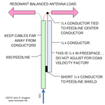
 

No it is probably not peer-reviewed, a bit too basic knowledge. These types of baluns built by combining odd quarter-waves of coaxial cable in different configurations is a special case of transmission line calculation that is very simple to calculate compared to other lengths of a transmission line. Zsource*Zload=Zline*Zline.
Most simple coaxial balun is the 1:4 balun, and then is it the 1:1 balun you have found.
I'll try to explain:

Zsource 50 Ohm is split in two coxial arms. If both these arms have impedance 100 Ohm do they together represent a 50 Ohm impedance against Zload (no mismatch).
But if they should have 100 Ohm in that 1/4-wave end, what impedance should it be 1/4 wave closer to the antenna?

Setting values in the formula from above:
100*Zload=50*50 => Zload = 25 Ohm.
The other arm is 1/2 wavelength longer which results in polarity shift but no further impedance shift. Let us call it for -25 Ohm.
Difference between these both arms is then equal to a 50 Ohm balanced load.

It is also common to combine coaxial cables with different impedance and get almost any impedance-ratio.
A similar configuration, which also have similar function, is to use 1/4 wavelength coax cable/or any thing, as sleeve choke.
baluns_sidestub1.png
As you can see it also results in a kind of 1:1 balun. Some may prefer to call it a "unbalanced current suppressor" rather then a pure balun,but result is almost the same.
Finally can you do nothing except wind last length coaxial cable, near antenna, into a tight coil. Also a kind of 1:1 balun but this one can be real broadband.

This is another fun way to do it:
1fig13.jpg
Not the best picture but antenna feed is from tip of one arm and shield on the other arm.
 
Last edited:
  • Like
Reactions: FvM

    FvM

    Points: 2
    Helpful Answer Positive Rating
Then it says "As the electrical length of both sections include the ¼ wavelength coaxial transformer, and if the unbalanced impedance has the same value of the coaxial cable, then the impedance seen at the other extremes is exactly the same value." Well, if the impedances are the same, we don't need any coaxial transformer.
So basically, unless I'm mistaken, this article is seriously flawed, in its technical arguments, although I'm not saying the design does not work.

Dave

Ahhhh but you are missing the point !! A BALUN doesnt necessiarily have to change the impedance from one to another eg. 50 E to 75 E etc
IT States a 1:1 BALUN that tells you there is no impedance change :) its just providing a match between an unbalanced 50 E coax and a balanced 50E antenna feedpoint

sometimes they are used for impedance transformation other times purely as an RF choke. That design is a complex way to do it, but if it works cool

The other main use of a BALUN is to stop RF current from flowing on the shield (screen) of the coax ( an RF choke). Therefore stops the shield from radiating, which is a bad thing


Dave

---------- Post added at 04:09 ---------- Previous post was at 04:03 ----------

This article

https://www.qsl.net/i0jx/balun.pdf

basically has the same design.

The first BALUN in that article , the 50E to 200E one is as said VERY common both in amateur and commercial systems
its a very easy way to match a 50E coax to a folded dipole driven element in a Yagi.

Dave
 
Last edited:

If you analyze the suggested 1:1 balun in detail, you'll notice that it basically works, but a common mode current through the λ/4 and 3λ/4 segments is involved. In case of Fig.2 of the second link, a common mode component will travel down the fed cable and also change the dipole radiation pattern. If the grounds of both coax segments are shorted against each other, "only" the cable segments will be possibly radiating.

Thus I agree with Dave, that some properties of the 1:1 balun design are hidden in the publications.
 

A bit of the problem is maybe that it is coaxial cables. Many of us are more used with structures like this:
0405m31_fig01.jpg
More about this circuit
This type of circuits do we often analyze in simulator tools and it feels natural as long as it is +GHz as it results in reasonable sizes.
Same thing translated to 10 MHz and a PCB filled with quarter wave traces would require a less practical size.
Along these quarter-wave lengths are points that not should be grounded or interconnected, both as PCB trace and coaxial wire, but even if that happen do it in worst case cost a few dB less good balance and a dB or two in extra loss, but can also result in an phase error. It is still a minor problem for an normal antenna, but this type of circuits are often used in mixers (as in the link above) and then can a few degrees phase error be very bad.
This phase problem is due to that velocity of a RF current is slower inside a coaxial cable compared to a signal that travels along outer shield.
 

This is the design I've seen in the past for 1:1 balun (I haven't assembled it), based on a Ruthroff paper.
It would be assembled with a coax and a single extra winding. Alternatively the coax could be replaced with
two wires in good intimate contact (or twisted) to form a transmission line with the characteristic impedance you
want.
balun_pic.jpg
There is so much astonishingly bad stuff written (e.g. most of the comments from W6E.. at https://www.eham.net/articles/24502 ) that it is depressing that there is not enough good links to learn more...
 
  • Like
Reactions: FvM

    FvM

    Points: 2
    Helpful Answer Positive Rating
No it is probably not peer-reviewed, a bit too basic knowledge. These types of baluns built by combining odd quarter-waves of coaxial cable in different configurations is a special case of transmission line calculation that is very simple to calculate compared to other lengths of a transmission line. Zsource*Zload=Zline*Zline.
I know that formula, and on several occasions have made an air-spaced coaxial section from brass rod & tube to have the impedance I want. Last time it was 60 Ω to match a dipole (impedance around 73 Ω) to 50 Ω Ohms. sqrt(50*73) = 60.3

Although that's all very basic knowledge, and at one point in time I could have derived it from first principles, the balun is a lot more complex than the quarter wave transformer. I think a peer reviewed analysis of the balun would be useful. A combination of theory and experimental measurements could easily form a MSc thesis. (I got both my MSc and PhD decades ago, but if anyone was looking for an interesting MSc project, I think there could be something done with baluns). There seems to be a lot written about them (mainly by radio hams), but I'm not convinced of the accuracy of a lot of the information. I've nothing against radio hams (I'm G8WRB myself), but they do then to write a lot of **** about antennas.

Most simple coaxial balun is the 1:4 balun,

Yes agreed, the 4:1 balun is relatively easy to understand. Note also that it would appear the impedance of the coax needed for the half-wave section is irrelevant, as you are only trying to get a 180 degree phase shift, yet

https://www.qsl.net/i0jx/balun.pdf

says the coax has to be 50 Ω. I don't think that's true.

and then is it the 1:1 balun you have found.
I'll try to explain:

Zsource 50 Ohm is split in two coaxial arms. If both these arms have impedance 100 Ohm do they together represent a 50 Ohm impedance against Zload (no mismatch).
Yes, if you combine two 100 Ohm terminations it will be 50 Ohms, but I don't understand where the 100 Ohms comes from, despite I do know how a quarter wave transformer works.
But if they should have 100 Ohm in that 1/4-wave end, what impedance should it be 1/4 wave closer to the antenna?

Setting values in the formula from above:
100*Zload=50*50 => Zload = 25 Ohm.
The other arm is 1/2 wavelength longer which results in polarity shift but no further impedance shift. Let us call it for -25 Ohm.
Difference between these both arms is then equal to a 50 Ohm balanced load.

I have a difficulty in understanding what impedance is presented at the end of the cable near the antenna, since there is no obvious (to me at least) defined value of impedance between the inner and outer conductors of the coax. I really don't have a clue there.

Even if I accept this does make some sort of 1:1 device, what makes it a balun? The input impedance looking into one end of an arbitrary length of 50 Ω cable, terminated in 50 Ω, will be 50 Ω. But an arbitrary length of 50 Ω cable does not make a balun!

It is also common to combine coaxial cables with different impedance and get almost any impedance-ratio.

Thank you. I'd never thought of doing that, but can see that the impedance would change by this. The equations to calculate it would be more complicated, but it's not rocket science.

A similar configuration, which also have similar function, is to use 1/4 wavelength coax cable/or any thing, as sleeve choke.
View attachment 72364
As you can see it also results in a kind of 1:1 balun. Some may prefer to call it a "unbalanced current suppressor" rather then a pure balun,but result is almost the same.

I believe there are some subtleties with this too. The usual way to make this is with a sleeve around the coax. I read somewhere the inner diameter of that needs to be large compared to the outer diameter of the coax, so you make a high-impedance transmission line. So you can't for example get good results by using that self-adhesive copper tape and sticking it on the outside of the jacket of the coax. I don't believe it will work too well with just a quarter wave wire as shown either, although I admit to not having tried it.


Finally can you do nothing except wind last length coaxial cable, near antenna, into a tight coil. Also a kind of 1:1 balun but this one can be real broadband.

But that is not a balun. Whilst it will stop the coax radiating so much, it does this by acting as a high impedance choke. The fact you reflect the radiation, just means it will screw up the radiation pattern of the antenna. I'm trying to design an antenna which has a defined radiation pattern. So whilst I appreciate this is not such a critical function as for the mixer someone else mentioned, I don't like the choke idea much.

Actually, I found two completely different explanations of how to make this coiled up bit of coax work on the web. A quick Google did not turn up what I found earlier today, but two explanations I see earlier were:

1) The length of the cable is critical (I did not take note of what it was supposed to be), but the author claimed it does not matter how you wind it on the former. So you can use a few turns on a large diameter former, or more turns on a small diameter former, as long as the overall length is whatever was stated.

2) The inductance of the coil should resonate with the distributed capacitance.

I suspect (1) is a load of rubbish, and (2) probably does have merit, as a parallel tuned circuit would have a very high impedance - far greater than you will get from just a the inductance of a coil. Of course, it would be quite difficult to calculate theoretically how to wind it for a given self-resonate frequency, but measuring it with a grid dip oscillator would work. (I have at work a VNA, so finding the self-resonate frequency of things like this is quite easy. If you put a small loop on the end of a bit of coax, and couple that near a resonate structure, you will see a dip in S11, as power is coupled into the structure. It's a bit of overkill, but I don't have a GDO at work, but I do have a VNA! At home unfortunately the situation is reversed. I have a GDO, but no VNA. If anyone with a VNA they don't want, needs a GDO. I'm happy to do a simple swap! )

This is another fun way to do it:
View attachment 72363
Not the best picture but antenna feed is from tip of one arm and shield on the other arm.

I can't say i understand how that works either. I'm not saying it does not - it's just not obvious to me personally.


Dave

---------- Post added at 23:07 ---------- Previous post was at 23:02 ----------

If you analyze the suggested 1:1 balun in detail, you'll notice that it basically works, but a common mode current through the λ/4 and 3λ/4 segments is involved. In case of Fig.2 of the second link, a common mode component will travel down the fed cable and also change the dipole radiation pattern. If the grounds of both coax segments are shorted against each other, "only" the cable segments will be possibly radiating.

Thus I agree with Dave, that some properties of the 1:1 balun design are hidden in the publications.

If you have a detailed analysis, can you post it?

I was thinking of making that 1:1 balun, but putting the two pieces of coax close together, as I have space restrictions. If they are radiating, they will couple to each other, which might mess things up even more. This is certainly not such a simple problem as some seem to claim.

Dave

---------- Post added at 23:35 ---------- Previous post was at 23:07 ----------

There is so much astonishingly bad stuff written (e.g. most of the comments from W6E.. at https://www.eham.net/articles/24502 ) that it is depressing that there is not enough good links to learn more...

Yes, there is a lot of rubbish written on the web about antennas by hams.

The truth is, that just about anything will function as an antenna, and in some cases you will get quite considerable distances with just about anything. So the fact some ham manages to work another on the other side of the earth, does not mean he has a good antenna. I recall once as a laugh using two wires on a barbed wire fence as an antenna. These were shorted together at various places, were uninsulated on wet wooden support posts. I could hear stations from Canada whilst on the Isle of Skye off the coast of Scotland, but never managed to work any on 100 W. But I worked several European stations, on what was basically the worst possible antenna I could have possibly made if I had tried.

Someone once said to me the difference between a good antenna and a bad antenna is usually not more than 20 dB. I suspect he is right. The truth is, that very often S/N ratios are such that 20 dB loss does not matter. But I don't like designing antennas like that!

I earn my living designing antennas, but I know my limitations. But it seems for many hams, writing what they think they know comes naturally.

To put it in engineering terms, the S/N ratio of articles about antennas on the web is so low, that you have difficulty in digging the signal (good articles) from the noise (crap articles). Some one can look at and immediately tell are rubbish, but on other occasions i simply have no idea.


Dave
 
Last edited:

Good thread; hopefully we can document some interesting findings on Baluns here.

The coiled up coax does make a balun, apparently because the coil does act as a choke only for all waveforms that are not passed as part of the transmission line action. The choke action therefore performs the isolation between input and output.
I found that described in the attached pdf doc (found that somewhere on the internet, I can't remember where). View attachment More On The 1-1 Balun.pdf
Anyway the paper that would explain it is by Guanella in Brown-Boveri Review Vol 31 Sep 1944, but I have never found that paper
(and I think I spent a week searching for it on the internet). Many people seem to reference that paper, but it appears next to
impossible to find : (
 
Last edited:

I reviewed my previous analysis (using SPICE transmission line segments) and realized, that my statement in post #4 is wrong in one important point. There's effectively no common mode wave, the 1:1 balun works perfectly at the center frequency. The operation is exactly as E.Kafeman wrote in post #2. Sorry for causing confusion.

Here's the revised simulation schematic:


The problem was, that I saw a common mode signal in simulation, but didn't ask for it's magnitude, or more exactly, power. Because the simplified model assumes infinite common mode impedance for the coax cable, a small numeric simulation error "fakes" a common mode signal. By connecting a common mode load impedance (R4 in the schematic), you see, that it's effectively zero.

Of course, this can be seen from a simple impedance transformation consideration as well, see post #2. So the only limitation of the shown balun is limited bandwidth. The transmission line transformer suggested in post #6 is superior in this regard.
 
Yes agreed, the 4:1 balun is relatively easy to understand. Note also that it would appear the impedance of the coax needed for the half-wave section is irrelevant, as you are only trying to get a 180 degree phase shift, yet https://www.qsl.net/i0jx/balun.pdf says the coax has to be 50 Ω. I don't think that's true.
No he doesn't say so. He says "all cable is 50 Ohm". You can use any cable impedance but you will get impedance ratio according to this.
Yes, if you combine two 100 Ohm terminations it will be 50 Ohms, but I don't understand where the 100 Ohms comes from, despite I do know how a quarter wave transformer works.
Antenna impedance is 50 Ohm. Split in 2*25 Ohm. Each coaxial cable will be loaded with 25 Ohm from antenna.
Insert these values in the formula 25*Zsource=50*50 => Zsource = 100 Ohm.
As you had an VNA, do the measurement. This type of problem is even simple to solve in a Smith chart.
I don't believe it will work too well with just a quarter wave wire as shown either, although I admit to not having tried it.
Try it, really do it, do not just sit there I say "maybe maybe not". I dare to say that any reasonable professional antenna designer know how it works both theoretical and practical.
Can not think about any RF engineer that had done some practical design that not have done a similar antenna design. A bit like doing your own basic tools. At least for me is it a basic antenna type, that I use every day as a reference antenna. Basically my whole measurement range is calibrated with simple homemade antennas. About once a month do I calibrate these antennas against a Schwarzbeck dipole antenna, but these certified reference antennas are to expensive for use for the daily calibration.
The usual way to make this is with a sleeve around the coax. I read somewhere the inner diameter of that needs to be large compared to the outer diameter of the coax, so you make a high-impedance transmission line.
You have read... Try to get some facts, not somewhere rumors. It is not an extension of the coaxial cable, neither is it some kind of shielding. Besides possible increased resistive losses is it perfectly ok to use a thin wire (or a reasonable thick tube). Look at it as two parallel wires with opposite direction of the RF signal. Wire isolation distance is not critical. A tube or a thin wire gives almost the same electrical result and it is simple to verify with a VNA. A example of a Wlan antenna with this type of balun and that cost around 4000$:
PD1850.jpg
This type of antennas are mostly used for calibration of other antennas.
But that is not a balun. Whilst it will stop the coax radiating so much,
With some black box logic, if measured Sxx results in every aspect are as if it was a balun.. It is a also a bunch of coaxial wire that causes extra transmission losses and some mismatch, especially as it is bent, but many other baluns do also have losses. If coaxial cable is winded on a magnetic core can it be very effective as balun. No, it is not a resonant circuit, it is preventing signals passing along the outside of the braid.
The last example is a Collins balun. The name is from the famous Collins radio, which first did describe its function during 1942. It is a very practical balun when the antenna feeding points have long distance apart.
Yes, there is a lot of rubbish written on the web about antennas by hams
Hams are often not professional antenna designers, they have not always any theoretical knowledge and works with simple measurement tools. Most of them share practical experience, as a kind of DIY instructions.
As professional antenna designer, are these ham-pages in internet not a way to find alternative to Maxwell s equations or Balanis book.
It is however for me often a inspiration and some problem can I recognize in my own work. Hams do mostly operate below 10 MHz so it is hard for them to find space for full size antennas. Same for me, I design mostly embedded antennas above 800 MHz, my antenna space is typical 5*10*30 mm and in that space should it maybe fit a pentaband antenna with efficiency max 3 dB less then a full size dipole for each frequency range. Each new project is full of new problems to solve. For some of these problems have I several times found, if not solutions but valuable ideas at just hampages.
These ham-operators dare to try to find creative solutions, even if it not is with full knowledge how and why. Even some balun-thinking have I borrowed, but I must of course translate 10 meters RG8 to 10 mm microstrip at a PCB. The ARRL handbook was the first antenna book I bought. It did give me enough antenna understanding, making it possible for me to understand heavier books.
Some of the most qualified antenna engineer that I know, are also HAM operators, so technical level of ham-pages can be anything from pure amateur to a very professional level and frequency can cover everything from ELF to 24 GHz. As many HAMs also builds their own rig, even at 24 GHz, is it not all so rubbish that someone think.
 
Last edited:
  • Like
Reactions: sky_123 and FvM

    FvM

    Points: 2
    Helpful Answer Positive Rating

    sky_123

    Points: 2
    Helpful Answer Positive Rating
Agree! A lot is incredibly good, I wish I hadn't said the the "lots is astonishingly bad" thing - I was referring to just the particular comments in the link. Even the ARRL guide + antenna guide are amazingly good value-for-money. Also, by the way, the 'Ham Radio' magazine is so good (I'm not from the US, so I had not seen it until recently). It is possible to buy a DVD containing all 130-odd scanned copies of it, and it is an amazing reference, with material in it by Rohde and others. I keep it on a USB stick. And I would never have built any receiver or transmitter from any paper, had it not been for all the practical stuff that hams were doing that paved the way...
 
It is possible to make a balun with a 1:1 impedance transformation from coaxial cable?

This article

https://www.iw5edi.com/ham-radio/files/I0QM_BALUN.PDF

...
Dave

Dave, notice the topology of that network resembles that of a rat-race coupler, although there are differences such as missing 1/2 Lambda along one leg ... keep in mind the effect of 'power flow' (or energy flow) in understanding the design. Also note the output of the BALUN you reference is differential between two line segments and not to 'ground' as in the rat-race (or hybrid ring) coupler (related also to the microwave "Magic Tee" coupler). Between the 'power flow' aspect and the impedance transformation effect a 1/4 wave length of line has ... transforming 1/2 of 50 Ohms at the 'load' (25 Ohms) to 100 Ohms for each side in parallel (making 50 Ohms) I would say it works ...

https://en.wikipedia.org/wiki/Rat-race_coupler


RF_Jim
 
Last edited:

Good thread; hopefully we can document some interesting findings on Baluns here.
...
Anyway the paper that would explain it is by Guanella in Brown-Boveri Review Vol 31 Sep 1944, but I have never found that paper
(and I think I spent a week searching for it on the internet). Many people seem to reference that paper, but it appears next to
impossible to find : (

Just happened across it, the paper: G. Guanella in the Brown Boveri Review in September of 1944 -

https://docs.google.com/fileview?id...DQtNTIzZC00NzNmLTk3ZjctYWQzMDhjMzg0ZGE2&hl=en


RF_Jim
 
You are awesome : ) Just reading through it now!!
 

Status
Not open for further replies.

Part and Inventory Search

Welcome to EDABoard.com

Sponsor

Back
Top