Welcome to our site! EDAboard.com is an international Electronics Discussion Forum focused on EDA software, circuits, schematics, books, theory, papers, asic, pld, 8051, DSP, Network, RF, Analog Design, PCB, Service Manuals... and a whole lot more! To participate you need to register. Registration is free. Click here to register now.
my project is temperature controlling automation..
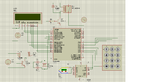
i hv used pic 18f4550
j thermocouple
3x4 keypad
my circuit is like this
cam any1 tell me is it right???
As per my understanding you are using thermo-couple for detection of temperature....Also your instrumentation amplifer circuit AD594 is uncomplete ....In my view the output of AD594 will be analog voltage so better to give this signal to adc pin of mico-controller....so you can do interfacing....
that what I was saying to you in your circuit the output of Instrumentation amplifer AD594 is analog singal...as per I understand the datasheet.... so connect is to ADC input pin ( any of the Port A pin RA1 , RA2 ,RA5 , RA6 or RA7) of Micro-controller and also keep the Vref(Port A- RA3 and RA4 for detection referecen) of the Micro-controller avalible for your detection.....then you can interface the Instumentation amplifer to Micro-controller....otherwise you will not able to get the reading from the thermo-couple....rest every thing is managable bcz every thing will be digital.....that what I think....
ok.. but my pic controller has inbuilt ADC... so dat no need to connect any ADC inbetween....now i m coding for my project thanx for d help..if i got any doubt i'll ask u if u dont have any prob...
thanx
Yes dear......when you want to use internal ADC you need to give reference voltages also to that ADC....I hope you understand what I am saying.... ok ....I understand that you are using RA5 for ADC detection....
This site uses cookies to help personalise content, tailor your experience and to keep you logged in if you register.
By continuing to use this site, you are consenting to our use of cookies.