Continue to Site

Welcome to EDAboard.com

Welcome to our site! EDAboard.com is an international Electronics Discussion Forum focused on EDA software, circuits, schematics, books, theory, papers, asic, pld, 8051, DSP, Network, RF, Analog Design, PCB, Service Manuals... and a whole lot more! To participate you need to register. Registration is free. Click here to register now.

What is this... Appreciate any help.

Status
Not open for further replies.

dieselfuelonly

Newbie level 4
Joined
Oct 25, 2011
Messages
6
Helped
0
Reputation
0
Reaction score
0
Trophy points
1,281
Activity points
1,329
Can somebody please tell me what in the hell this thing is... before I chuck the whole truck out the window. It's in the way of what I'm what i'm trying to do, and repairing it seems to be short of impossible. What is it, what does it do, and can i do away with it?

Sorry for the pic I don't have a decent cam at the moment. The part in question is about 3/4 of a centimeter long.
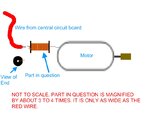
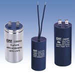
diagram.jpeg
 

Hi,

This looks like motor choke! (Electrical)


But tell me the following :

You didnt say how big is that motor and that cable.
This motor is used for what ? (purpose, what device)
Motor works on DC or AC and what voltage ?
Do You see clearly that part, is it the same like on Your picture (like solenoid) or look like this :

Motor-Capacitor-CBB60-.jpg


Or look like this :

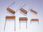
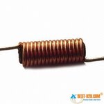
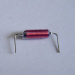
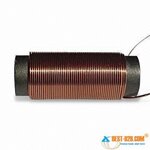
Choke_coils_for_removing_motor_noises.jpg choke-coil-873.jpgchoke coil.JPGchoke-coil-409.jpg

I give answer on Your next future question:

A choke is a coil of insulated wire, often wound on a magnetic core, used as a passive inductor which blocks higher-frequency alternating current (ac) in an electrical circuit while passing signals of much lower frequency and direct current by having an impedance largely determined by reactance, which is proportional to frequency (see Inductor and Inductance). Chokes are typically used as the inductive components in electronic filters.
A "choke" is the common name given to an inductor that is used as a power supply filter element. They are typically gapped iron core units, similar in appearance to a small transformer, but with only two leads exiting the housing. The current in an inductor cannot change instantaneously; that is, inductors tend to resist any change in current flow. This property makes them good for use as filter elements, since they tend to "smooth out" the ripples in the rectified voltage waveform.

Why use a choke? Why not just a big series resistor?

A choke is used in place of a series resistor because the choke allows better filtering (less residual AC ripple on the supply, which means less hum in the output of the amp) and less voltage drop. An "ideal" inductor would have zero DC resistance. If you just used a larger resistor, you would quickly come to a point where the voltage drop would be too large, and, in addition, the supply "sag" would be too great, because the current difference between full power output and idle can be large, especially in a class AB amplifier.

The name comes from blocking—"choking"—high frequencies while passing low frequencies. It is a functional name; the same inductor is often called a "choke" if used to block higher frequencies, but a "coil" or "inductor" if, say, part of a tuned circuit.

A common mode choke may be used to reduce a type of electrical noise known as common mode noise.

Electro-magnetic interference (E.M.I.) in the circuit's environment is one source of electrical noise. E.M.I. induces or couples unwanted electrical signals into the circuit. It is desirable to filter out the unwanted noise signals without
significantly affecting the desired signal. Environmental sources of E.M.I. often create an independent return path (ground path) for the electrical noise signals. The return path of the desired signal is a different path. Because there are two different return paths, a Common Mode Choke can be used to significantly block (hence reduce) the unwanted noise signal (at the load) without significant reduction in the desired signal.

A.C. Power Lines provide a good example. They are known to carry significant levels of electrical noise. Their long length gives environmental E.M.I. ample opportunity to generate unwanted electrical noise into the power lines.

Capacitor input or choke input filter?

There are two common power supply configurations: capacitor input and choke input. The capacitor input filter doesn't necessarily have to have a choke, but it may have one for additional filtering. The choke input supply by definition must have a choke. Capacitor input filters are by far the most commonly used configuration in guitar amplifiers (in fact, I can't think of a production guitar amp that used a choke input filter).

The capacitor input supply will have a filter capacitor immediately following the rectifier. It may or may not then have a second filter composed of a series resistor or choke followed by another capacitor. The "cap, inductor, cap" network is commonly called a "Pi filter" network. The advantage of the capacitor input filter is higher output voltage, but it has poorer voltage regulation than the choke input filter. The output voltage approaches sqrt(2)*Vrms of the AC voltage.

The choke input supply will have a choke immediately following the rectifier. The main advantage of a choke input supply is better voltage regulation, but at the expense of much lower output voltage. The output voltage approaches (2*sqrt(2)/Pi)*Vrms of the AC voltage. The choke input filter must have a certain minimum current drawn through it to maintain regulation.

The voltage difference between the two filter types can be quite large. For example, assume you have a 300-0-300 tranny and a full-wave rectifier. If you use a capacitor input filter, you'll get a no-load max DC voltage of 424 volts, which will sag down to a voltage dependent on the load current and the resistance of the secondary windings. If you use the same transformer with a choke input filter, the peak output DC voltage will be 270V, and will be much more highly regulated than the capactor input filter (less variations in supply voltage with variations in load current).


How to select a choke:


Chokes are typically rated in terms of max DC current, DC resistance, inductance, and a voltage rating, which is the max safe voltage that can be applied between the coil and the frame (which is usually grounded).

DC current
If you are using a choke-input filter (not likely, unless you are trying to convert a class AB amp to true class A and need the lower voltage, or if you are designing an amp from scratch and want better supply regulation), the choke must be capable of handling the entire current of the output tubes as well as the preamp section. Note that this doesn't mean just the bias current of the output tubes, but the peak current at full output. This usually requires a choke about the size of a standard 30W-50W output transformer, since the choke must have an air gap (just like a single-ended OT) to avoid core saturation due to the offset DC current flowing through it, and the choke also must have a low DC resistance, to avoid dropping too much voltage across it, which will lower the output voltage and worsen the load regulation. This combination of low DCR, air gap, and high inductance (more on that later...) usually results in a substantial sized choke. To calculate the required current rating, add up the full power output tube plate currents, screen currents, and the preamp supply currents, and add in a factor for margin. For a 50W amp, this may be 250mA or so.

If, on the other hand, you are selecting a choke for a capacitor input supply (such as the typical Marshall or Fender design), then the requirements are relaxed quite a bit. The purpose of the choke in these type supplies is not for filtering and voltage regulation, but just for filtering the DC supply to the screen grids of the output tubes and the preamp section. The screens typically take around 5-10mA each, and the preamp tubes draw about 1-2mA or so (for the typical 12AX7; 12AT7's are usually biased for around ten times that). This means that you can get by with a much smaller choke, and, in addition, the preamp supply current doesn't vary that much, so you can get by with a higher DC resistance, which means smaller wire can be used to wind the choke, which means higher inductance for a given size core. Just add up the current requirements of the screens and preamp tubes, and add a bit more for margin. For a 50W amp, a typical value might be 50-60mA.

DC resistance
For a typical choke input supply, you need a choke with no more than 100-200 ohms or so DCR. A capacitor input supply typically might use a choke with a 250 ohm - 1K DCR. The higher the resistance, the more voltage drop and the poorer the regulation, but the cost will be lower.

Inductance

As for the inductance value, this depends on how much filtering you want. The inductance, in conjunction with the filter capacitance, forms a lowpass filter. The larger the inductor, the lower the cutoff frequency of the filter, and the better the rejection of the 120Hz (if full wave rectified) or 60Hz (if half wave rectified) AC component of the rectified DC. In general, the larger the better, within reason (larger inductances at low DC resistances mean larger chokes, which cost more money). Typically, 5-20 Henries is a good choice with the standard 32-50uF electrolytic capacitors. The inductance and capacitance values also determine the transient response of the supply, which means the tendency for the supply to overshoot or "ring" with damped oscillations whenever a current transient is applied (such as at startup or on a heavy current surge, such as a hard "E" chord at full power!).

Voltage rating
The voltage rating must be higher than the supply voltage, or the insulation on the wire may break down, shorting the supply to the frame.
 
Last edited:
  • Like
Reactions: ggmssr

    ggmssr

    Points: 2
    Helpful Answer Positive Rating
It looks exactly like it does in my picture. The motor it goes to drives the front axle in an rc truck that I'm overhauling. My dumb self pinched the wire bundle at one point, severing the red one at the point shown in my picture.

Edit: now that I see your full post, it appears to be a choke coil.
 

I'm 19 and just getting into messing with rc's. To this point I was swapping tires and altering bodies. Now I'm altering the suspension on my current project (from fixed spring to rock crawler style) I'm good at it and I do quality work. For example, I've made a makeshift winch operated by the mainboard and front axle motor from an old gutted rc from my childhood (can't remember why I tore torn apart...) But anyway, keep that in mind when I ask this: Can I do away with the choke and solder the wire directly to the motor where the choke was soldered?
 

Thank you very much for the help, I greatly appreciate the decency (I asked a guy at work and he told me I should know the answer to that if I plan on messing with rc's...) So thank you. While I'm at it, I have one more question. That winch I mentioned earlier is powered by a 9 volt battery zip tied to the under carriage. The winch works strong and pulls my truck, but it rips and tears around because of all the torque. Is there anything simple I can do to reduce the rpm of the winch, while keeping the pulling power?
 

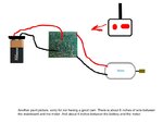
I'm sure this isn't helping much but here...

edit: typo'd in the pic, I meant to type "4 inches of wire between battery and mainboard"

diagram2.jpg
 

This depends on that motor, whether it can be run on lower speed and lower current/voltage. This require new circuit which will give control and monitoring of that motor. You can for first aid search dc motor speed control circuit.
 

Status
Not open for further replies.

Part and Inventory Search

Welcome to EDABoard.com

Sponsor

Back
Top