Continue to Site

Welcome to EDAboard.com

Welcome to our site! EDAboard.com is an international Electronics Discussion Forum focused on EDA software, circuits, schematics, books, theory, papers, asic, pld, 8051, DSP, Network, RF, Analog Design, PCB, Service Manuals... and a whole lot more! To participate you need to register. Registration is free. Click here to register now.

PWM Inverter for solar application

Status
Not open for further replies.

youcef2010

Member level 1
Joined
Oct 28, 2011
Messages
32
Helped
1
Reputation
2
Reaction score
0
Trophy points
1,296
Location
Tunisia
Activity points
1,519
Dear All,
Greetings
This is my first log into this well reputed forum, I hope you welcome me,
My Problem is as following,
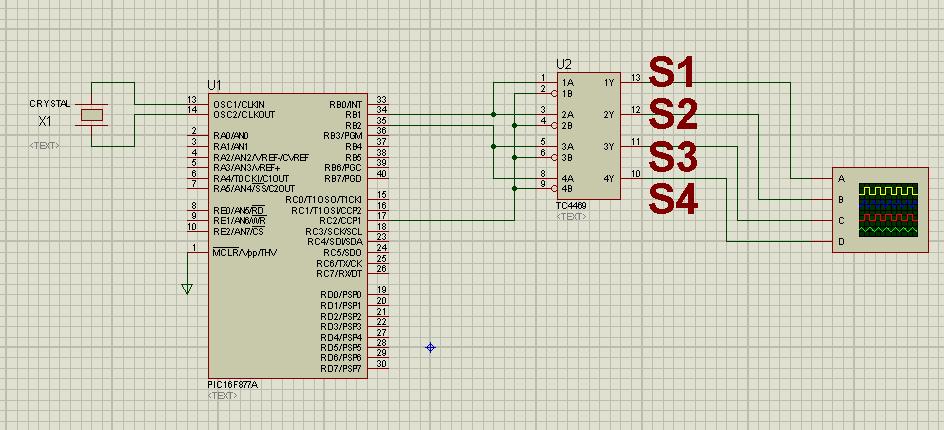
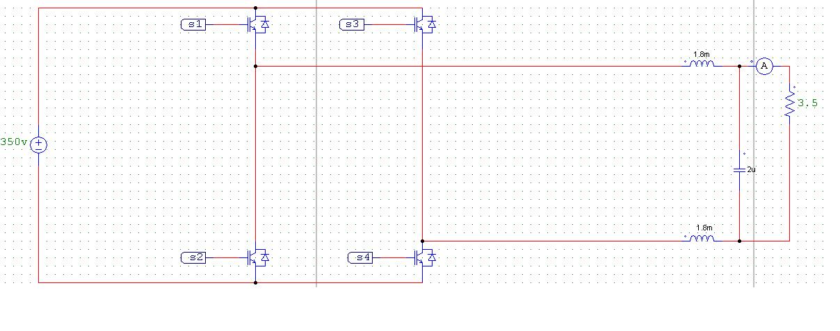
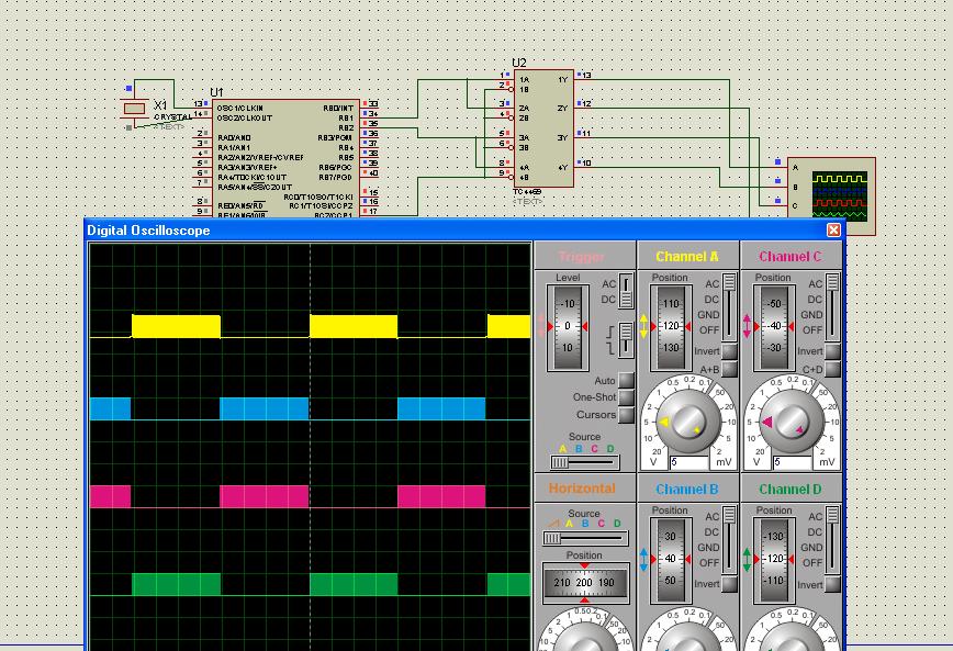
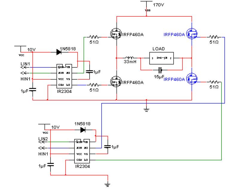
I have generated PWM from PIC16F877A and to drive the inverter MOSFETs, you need gate isolation circuit, I have used optocoupler but the MOSFETs do not switch. When I replaced MOSFETs with NPN transistor, the inverter works but when I change the voltage of collectors, nothing happen and the inverter output does not exceed 2v pk-to-pk !!!!
Please, somebody seen something like that before.
 

Of course You are welcome here.

Can we see Your circuit, to see is there problems in design.
 
Last edited:

Dear tpetar,
Thank you very much for your reply,
I need the best way to drive MOSFETs, please provide the entire driving circuit if possible. I tried to use IR2110 but I could not.


Sorry my friend, I was in the crowd.

I didnt catch link between this circuit and solar application. On second circuit where are MOSFETs you use high voltage.

Do You whant to make power inverter 12V to 220V is this goal ? (from solar panels or batteries)
 
Last edited:

Dear Sir,
Yes I want to make a transformerless inverter 12v to 220v for use in photovoltaic applications. In the second circuit there are 4 IGBTs instead of MOSFETs.
 

Dear Sir,
Yes I want to make a transformerless inverter 12v to 220v for use in photovoltaic applications. In the second circuit there are 4 IGBTs instead of MOSFETs.

Look this circuits :
 

Attachments

  • !!! 500W low cost 12V to 220V inverter 4047 --- OBAVEZNO !!!!!!!.rar
    214.7 KB · Views: 205
  • !!! 500W Modified Sine Wave Inverter PIC16F628.rar
    1.8 MB · Views: 270
  • !!! ATMega8 Inverter.rar
    1.4 MB · Views: 267
  • !!! Inverter 24V to 220V.rar
    432.6 KB · Views: 259

Dear tpetar,
Kind regards,
Is it possible you look at circuit number one (PIC16F877A) and tell me how to connect pulse transformer to drive the IGBTs of circuit 2.
 

Dear tpetar,
Kind regards,
Is it possible you look at circuit number one (PIC16F877A) and tell me how to connect pulse transformer to drive the IGBTs of circuit 2.

I've already looked, thats the point, Your design is bad. You cant build this with Your design!!!

I send examples of inverters, on examples we learn.

Your complete concept is wrong on this two circuits what You give.


Inverter should looks like this :

Circuit2.jpg

Circuit3.jpg

Circuit.jpg

And if You whant DC on out You can do rectification with some bridge. Perhaps for plasma cutter I dont see other purpose of this, but only You know purpose of this.
 
Last edited:

Dear Sir,
I think some missuderstand is available between us, the plasma is just to show simulation results as shown in figure 1, actually the 4 control signals are used to drive the IGBTs through their gates. one way is to use IR2110 as shown in figure two, unfortunately, I could not do it.
 

    V

    Points: 2
    Helpful Answer Positive Rating
Dear Sir,
Yes I want to make a transformerless inverter 12v to 220v for use in photovoltaic applications. In the second circuit there are 4 IGBTs instead of MOSFETs.

You say this earlier.

This cant be done with Your Design Concept.

I hope so that You udnerstand basic concept how to step up voltage.
 
Last edited:
Dear Sir,
I think some missuderstand is available between us, the plasma is just to show simulation results as shown in figure 1, actually the 4 control signals are used to drive the IGBTs through their gates. one way is to use IR2110 as shown in figure two, unfortunately, I could not do it.


Hi Mr. teptar....

Are you using PWM in your code to generate AC wave from or it is a square wave based.....

I like your center tap trasformer idea....

with regards,

Milind
 

Here is complete with translation of text :

Circuit2.jpgCircuit3.jpgCircuit.jpg


From the presented scheme can be seen that the RB1 pin microcontroller via optocoupler IC3 causes the existence of power failure indication. If there is power to the inverter is in charging mode. Bright LEDs LED1 to indicate the existence of the 220 ​​V network. Also, LED lights and Led4 that, if the battery charge is done. Led diode LED3 indicates that the battery voltage below 10 V when the drive is off. In case if the temperature of the cooling plate output transistors is greater than 70 ° C LEDs will blink Led5 and the drive will also be turned off until the temperature falls below 70 ° C, and also hear the steady sound of the buzzers Bz1. Through the relay RE1 is done off the consumer if allowed temperature is exceeded, while the relay RE2 is used to switch customers to the network operation or inverter.

For the realization of the inverter mikrokontrolerskog essential elements provided in the table below.


Web address: MIKROKONTROLERI
 
hello tpetar,
The language shown on urs given diagram is understandable,can u plz write it in english so that one can be benefited or plz tell about to translate it.thanks
 

hello tpetar,
The language shown on urs given diagram is understandable,can u plz write it in english so that one can be benefited or plz tell about to translate it.thanks

Its on Serbian language written on latinic (we also writing on our native cyrilic).

Faza = AC Main Phase
Mreža = AC Line
Pretvarač = Inverter
Punjenje = Charging
Srednja sekundara = Middle of trafo secundar
Izlazni = Out
Srednji = Middle
Mrežni napon = AC Line
 

youcef2010,
In post #11 in your circuit you showed 170 volts input to the MOSFETS, is this input voltage you are using? If yes what output voltage you want? And which form, AC or DC?
Your question is confusing (atleast to me) make it clear first.
In your post #5 you said
Yes I want to make a transformerless inverter 12v to 220v for use in photovoltaic applications.
What output voltage you want and what is your supply voltage? The supply source is Photovoltaic panels or what?
If your input is 12 volts and you want 220 volts, how is it possible to get 220 volts without use of transformer?
 

youcef2010,
In post #11 in your circuit you showed 170 volts input to the MOSFETS, is this input voltage you are using? If yes what output voltage you want? And which form, AC or DC?
Your question is confusing (atleast to me) make it clear first.
In your post #5 you said

What output voltage you want and what is your supply voltage? The supply source is Photovoltaic panels or what?
If your input is 12 volts and you want 220 volts, how is it possible to get 220 volts without use of transformer?


I dont think that he know what he do.

He whant revolutionar transformerless 12V to 220V :shock:
 

Yes tpetar, it seems from his text that he on some revolutionary job. Wish he gets some :!:
But for response purposes I wanted if he could make it clear actually is in his mind.
 

hello tpetar
thanks for the translation u explained.
 

Youcef2010, in your first post can you elaborate,
but when I change the voltage of collectors
Your problem seems to be swithing sequence. Ensure when lower left fet is on then right upper mosfet should be on and when right lower fet is on then left upper fet should conduct.
S1,S3 and S2,S4 makes two pairs. You should revers either one of them. For example S1 for Hin1, S3 for Lin1 and S4 for Hin2, S2 for Lin2. If both lower are on for one time and both upper are on for other time, ther will be no output.
 
Status
Not open for further replies.

Similar threads

Part and Inventory Search

Welcome to EDABoard.com

Sponsor

Back
Top