Continue to Site

Welcome to EDAboard.com

Welcome to our site! EDAboard.com is an international Electronics Discussion Forum focused on EDA software, circuits, schematics, books, theory, papers, asic, pld, 8051, DSP, Network, RF, Analog Design, PCB, Service Manuals... and a whole lot more! To participate you need to register. Registration is free. Click here to register now.

Question about mixer input levels

Status
Not open for further replies.

obrien135

Full Member level 5
Joined
Nov 10, 2009
Messages
240
Helped
5
Reputation
10
Reaction score
5
Trophy points
1,298
Location
Connecticut
Activity points
3,259
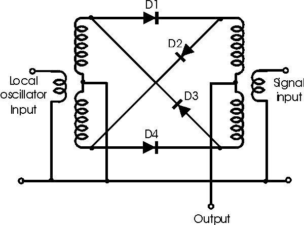
Does it matter if the local oscillator amplitude on a mixer input (about 9Vpp) is greater than than the IF on the other mixer input (about 3Vpp)? It is a diode ring modulator.
 

Normally for a mixer there is a optimum LO drive voltage that gives you low LO leakage at the output, this level should be applied to prevent unwanted LO signal.
This level is either specified in datasheet of mixer or it is measured by applying variable LO amplitude.Because LO-RF isolation is not infinite and nobody wants to see LO signal at the output spectrum.
 
If the LO is much greater than the IF, wouldn't you still get the RF on the output, along with the LO frequency? With the scope it's difficult to tell if the RF is there, but I don't get anything on the general purpose receiver when I transmit, when I tune the general purpose receiver to the RF frequency (or whatthe RF is suppoed to be). The IF and the LO frequencies are OK.
 

RF input to the diode ring in case of double balanced mixer is around -50dBm and LO is around 5dBm as per industry standards.
 
What if it mexes IF (3MHz) and LO (10MHz). would the ratios still be te same?
 

The input power levels impact the receiver sensitivity if your design is optimized for the best performance the RF of -90dBm and LO of -5dBm will also do as the LNA can boost the signal and also if Gilbert Cell is used conversion gain upto 20dB can be achieved.
 
With a 3Vpp IF signal and a 10Vpp LO applied to the mixer inputs, what kind of amplitude difference frequency should I expect to see on the mixer output? IF = 3MHz, LO = 10MHz.

A diagram of the mixer is below.


This answer depends on the diode param, type of hybrids used if in GHz range, losses like the insertion loss and the phase noise char.
 

I am getting 3MHz at the mixer input although it is a little jumbled by the 10MHz. And the 10MHz is present in full force. The mixer wiring appears to be good visually. My ohmmeter in on the fritz. But I am not getting the 7MHz out. It's for a 40M transceiver.
 

The little jumbled cause of bad port isolation.
I have a ques had you used a diode for 10MHz operation?
 
I did use the diode modulator for the 10MHz. What causes poor port isolation? What ports do you mean?

---------- Post added at 21:49 ---------- Previous post was at 21:24 ----------

I took more careful measurements and determined that the loss of the 3MHz is on the filter output (just prior to the mixer). The filter has the right components I will display a picture of it.

<center>
<a href="http://s279.photobucket.com/albums/kk130/obrien135/?action=view&current=3MHzbandpassfilter.jpg" target="_blank"><img src="http://i279.photobucket.com/albums/kk130/obrien135/3MHzbandpassfilter.jpg" border="0" alt="Photobucket"></a>
<br/><br/>
</center>

There's something wrong with my PC and I can't upload pictures. I tried photobucket as you can see but it didn't work. The filter has a 533ohm resister in parrallel with a 100pF cap as feedback (it's an inverting amp configuration using an LM7171). The input circuit is the same two component values, but in series. The math checks out. It's passing the 10MHz but rejecting the 3MHz. It's built on a perf board.
 
Last edited:

Could it have anything to do with using decoupling capacitors on the supply pins of the op amp chip? It's at another location, so I can't check right now so I'm not sure if I used some or not.
 

Normally the OpAmp power supply should have a Tan Capacitor 10uF at least and other capacitors.
Do you use OpAmp to amplifie signal? You can simulate to check the effect.
 

Thank you. It has unity gain in the pass band. I will try the capacitors. Normally wouldn't they diminish noise or spurious oscillations , but have little effect on how well it passes frequencies in the passband?
 

I did use the diode modulator for the 10MHz. What causes poor port isolation? What ports do you mean?
LO to IF, RF to IF and LO to RF are the ports that needs to be isolated. Double balanced diode mixers are the ideal for such purposes. Provides around 20 dB isolation.
 

I looked at the circuit today. It doesn't have decoupling capacitors, and I will deal with that also, but I am trying to find out why I am loosing the frequency that it is supposed to pass even though the components that determine the passband frequencies are correct. The only other thing that I can see that might be a problem is that I didn't use a coupling capacitor between the output of the filter and the primary of the transformer of the diode mixer. Would that primary (DC short) effect the biasing of the op amp in a bad way? Below is a link to a photo of the circuit diagram.

https://i279.photobucket.com/albums/kk130/obrien135/pictureforedaboard.jpg
 
Last edited:

Status
Not open for further replies.

Part and Inventory Search

Welcome to EDABoard.com

Sponsor

Back
Top