Continue to Site

Welcome to EDAboard.com

Welcome to our site! EDAboard.com is an international Electronics Discussion Forum focused on EDA software, circuits, schematics, books, theory, papers, asic, pld, 8051, DSP, Network, RF, Analog Design, PCB, Service Manuals... and a whole lot more! To participate you need to register. Registration is free. Click here to register now.

inverting charge pump + 7905 problem

Status
Not open for further replies.

poorchava

Advanced Member level 1
Joined
May 21, 2009
Messages
429
Helped
71
Reputation
142
Reaction score
71
Trophy points
1,318
Location
Wrocław, Poland
Activity points
4,780
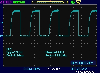
In my project i need a low power negative voltage source for powering opamps. I want to generate negative voltage from positive by using inverting charge pump and then regulating the pump's output with 7905 IC. Below is the circuit schematic:
30_1296434435.jpg


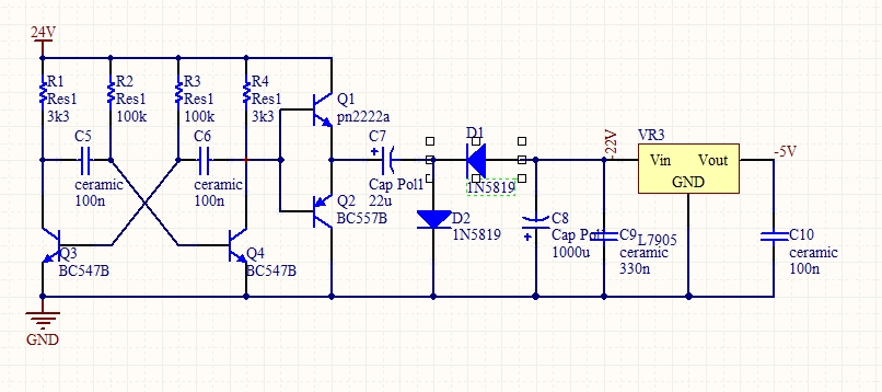
The pump generally works, it generates negative voltage and is capable of lighting a led with 2k2 resistor in series. The problem is with the regulator: it doesn;t work without sufficient load. Without load i've measured about -17V with respect to ground, while i've expected it to be regulated to -5V.

If load the regulator with a resistor of 270 ohm or so, the output voltage is correct, but otherwise it's not. Loading the regulator with 3k3 resistor make it's output about -9 volts.

I intend to power opamps only, which meansthat the regulator won't be loaded enough for it to generate proper voltage. Should i just attach 270ohm resistor in parallel with opamp power pins? And why is this circuit behaving in such a strange manner?

When i power the regulator from workbench adjustable power supply it works fine (always -5V), but when i power it from charge pump it does not. Whet is the proper solution of this problem?
 

I've never seen the 79xx regulators be that fussy.
But if I recall, their pinout is not the same as the
78xx; any chance you have something swapped?
Or just a bad part?
 

The part isn't bad, it works just fine wiehn connected to a normal transformer power supply.

And i know about swapped pins.
 

Something doesn't seem right with the regulator, normally their internal current is enough to maintain the output voltage and certainly, 3K3 is more than adequate to load it anyway. I suspect you have an instability problem. Are the capacitors at each side of the regulator very close to it, the manufacturers usually specify no more than 25mm away and are you using a common ground point for the capacitors, rectifiers and the regulator GND pin?

Brian.
 

the pump is assembled on a pcb, and the regulator is soldered in the air (i mean without pcb, leads soldered to each other, i don't know the exact english word for that). Capacitors are i their place. The calculated frequency at which the pump operates is about 142 Hz. Oscilloscope shows the following at the multivibrator output (before pump)
23_1296474280.jpg

I guess that means two things: it works as intended (more or less, i've noticed that frequency greatly depends on supply voltage) and i could've use some resistor to limit capacitor leading current (the curve on the rising edge)

With ragulator attached the output of multivibrator looks the same, so the regulator doesn't load or in any other way alter timing circuit. At the output of charge pump oscilloscope detects only DC of about -30V and about -18V at the output (albo pure DC).

I'm just running out of ideas...

edit:
come to think of it, as the pump outputs a nice, smooth dc voltage, i could power if from 5 or 7 volts positive regulator and then power opamps straight from the charge pump (the negavite voltage value isn't critical, it's just there to be able to get 0V from not-rail-to-rail opamp)
 

With such a low frequency oscillator you will find it works more efficiently if you increase the value of C7, alternatively make the oscillator run faster, I suggest nearer 1KHz. The reactance of C7 is more than 50 Ohms at 142Hz!

The instability I meant was actually in the 7905 itself, they contain a high gain amplifier in their control loop and if you inject a signal into it due to poor grounding, it can make them oscillate by themselves.

As your voltage doesn't have to be precise, I would recommend you use a Zener diode to stabilize the voltage. Connect the pump output through a resistor then clamp the voltage with the Zener to ground. It will give you better stability than just using the pump output alone. Calculate the resistor so the Zener passes about 2mA when the load on the pump is as high as it will ever reach, the diode will then drain remaining current if the load decreases.

I don't think there is an English way to describe the way you built it "up in the air" is as good anything!

Brian.
 

For the LM7905 National suggests an output capacitor of 1uF (solid tantalum) or 25uF (electrolitic). Yours is too small. Maybe the LM7905 is oscillating. I´ve had problems like yours when using small capacitors at both input and output. Negative regulators behave different when compared to the positive ones.
 

Your circuit has a 24V supply but the 'scope shows an output from the oscillator that is 33.6V p-p. Impossible!

If the oscillator transistors did not have avalanche breakdown then I think the output will be about 20V p-p if the load current is very low.

The oscillator transistors have a max allowed emitter-base reverse voltage rating of only 6V. But the coupling capacitors C5 and C6 charge to about 23V then try to slam the bases down to -23V causing the emitter-base junctions to have avalanche breakdown at a high enough currents to slowly destroy the emitter-base junctions.
 

24V volts supply is a mistake (an earlier version of design). At the moment pump is powered from mains to 2x9V 2x 120mA transformer. Secondary windings are connected in series and then rectified by full wave bridge and filtered by 1000uF/50V capacitor. When not loaded i measured about 30-34V at terminals of filtering capacitor. When significantly loaded (like a 1k resistor) the voltage falls down to about 26V.

I guess i'll just drop the charge pump idea, as i found some pcb mounted transformers at a bargain and bought a couple of them so i'll use them for that. Other idea is to use some IC charge pump with few external components (i know that Microchip produces such IC's)
 

Status
Not open for further replies.

Similar threads

Part and Inventory Search

Welcome to EDABoard.com

Sponsor

Back
Top