vioamethyst
Member level 3
what need to be taken into consideration?
what sort of impedance mathing need to be do? can help me?
i know that the transmission line together with the patch need to have total length of λeffetice so that the wave will be in phase throughout the array element
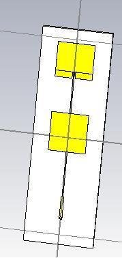
attach pic is the the sub array that will be use in my overall array design
the feeding is from coax (50 ohm) that with use the quarterwave impedance matchig of 73.3369 (1.43mm, 11.91mm) ohm to the transmission line feed on 107.5660 ohm (0.52mm,λeff/2 length) that will be use to connect to antenna
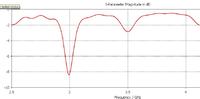
my antenna suppose to operate at 3.5 Ghz , but as u can see in the other attachment, the s11 happen to resonate at 3GHz
i guess its due to the refletion from the end antenna toward the source have make this "side" resonance, but the problem is...the resonant at my frequency is not achieve
please help me
i dun rili know how to match the impedance match need to folloow, and of cos i cannot use quarter wave impedance matching sine my line is λeff/2 long,
what thing i can refer to/suggestion to match the impedance of the transmision lines with the 2 patch/element ?
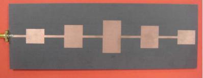
i also need some knowledge on you guys on how to do taper series feed antenna? i mean how u taper the impedance?? brief explaination (at teh very least) is appreciated well enough, here i attach photo from some jurnal that do, series fed taper antenna array...but i dun know how they taper the impedance, i mean based on what?
due to design limitation (the design in the pic is just the sub element of the overall design), i MUST use coax 50 ohm , and quarter wave impedance of 73.3369ohm
what sort of impedance mathing need to be do? can help me?
i know that the transmission line together with the patch need to have total length of λeffetice so that the wave will be in phase throughout the array element
attach pic is the the sub array that will be use in my overall array design
the feeding is from coax (50 ohm) that with use the quarterwave impedance matchig of 73.3369 (1.43mm, 11.91mm) ohm to the transmission line feed on 107.5660 ohm (0.52mm,λeff/2 length) that will be use to connect to antenna
my antenna suppose to operate at 3.5 Ghz , but as u can see in the other attachment, the s11 happen to resonate at 3GHz
i guess its due to the refletion from the end antenna toward the source have make this "side" resonance, but the problem is...the resonant at my frequency is not achieve
please help me
i dun rili know how to match the impedance match need to folloow, and of cos i cannot use quarter wave impedance matching sine my line is λeff/2 long,
what thing i can refer to/suggestion to match the impedance of the transmision lines with the 2 patch/element ?
i also need some knowledge on you guys on how to do taper series feed antenna? i mean how u taper the impedance?? brief explaination (at teh very least) is appreciated well enough, here i attach photo from some jurnal that do, series fed taper antenna array...but i dun know how they taper the impedance, i mean based on what?
due to design limitation (the design in the pic is just the sub element of the overall design), i MUST use coax 50 ohm , and quarter wave impedance of 73.3369ohm
