Welcome to our site! EDAboard.com is an international Electronics Discussion Forum focused on EDA software, circuits, schematics, books, theory, papers, asic, pld, 8051, DSP, Network, RF, Analog Design, PCB, Service Manuals... and a whole lot more! To participate you need to register. Registration is free. Click here to register now.
You may do these simulation..
-Output Voltage vs. Temperature
-Output Voltage vs Process Variations and Mismatch-Monte Carlo Simulation
-PSRR vs Temperature for different Compansation Capacitor if it's available
-Output Noise
-Start-Up vs Temperature with Corners Check<---- Very important
-Latch-Up Test
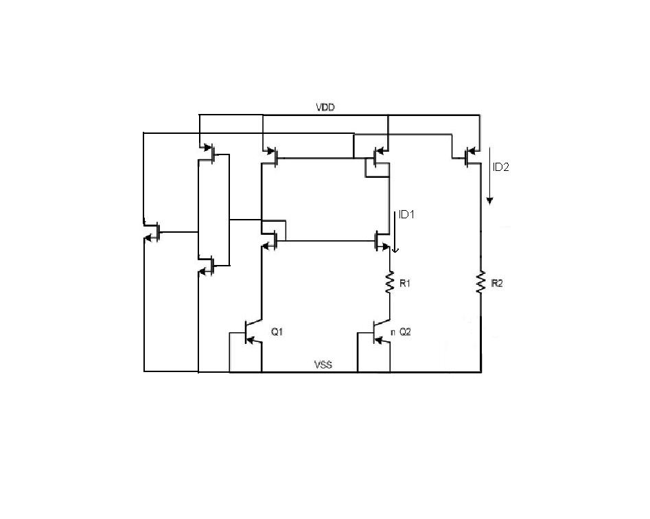
I simulate the PTAT circuit in the LTspice, not include the startup circuit on the left, I set the parameter L=2u, W=100u, n=8, VDD=3v, R1=R2=100ohmic, I found the current ID1 and ID2 are not the same, ID2 is very very small.
---------- Post added at 16:45 ---------- Previous post was at 16:39 ----------
You may do these simulation..
-Output Voltage vs. Temperature
-Output Voltage vs Process Variations and Mismatch-Monte Carlo Simulation
-PSRR vs Temperature for different Compansation Capacitor if it's available
-Output Noise
-Start-Up vs Temperature with Corners Check<---- Very important
-Latch-Up Test
I want to simulate a thermal temperature sensor by using a PTAT circuit to generate the bias current, then connect the current to a ring oscillator to generate the frequency, then count the frequency.
This site uses cookies to help personalise content, tailor your experience and to keep you logged in if you register.
By continuing to use this site, you are consenting to our use of cookies.