Continue to Site

Welcome to EDAboard.com

Welcome to our site! EDAboard.com is an international Electronics Discussion Forum focused on EDA software, circuits, schematics, books, theory, papers, asic, pld, 8051, DSP, Network, RF, Analog Design, PCB, Service Manuals... and a whole lot more! To participate you need to register. Registration is free. Click here to register now.

Coupling a Horn (circular) to a Polarizer (square) ??

Status
Not open for further replies.

Darktrax

Full Member level 5
Joined
Nov 28, 2009
Messages
287
Helped
103
Reputation
206
Reaction score
100
Trophy points
1,323
Location
UK
Activity points
5,268
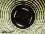
Our supplied 8GHz corrugated horn has a round exit hole, and is bolted directly onto the square aperture of a septum-type polarizer. This separates the RHCP and LHCP into two normal rectangular waveguides

The diameter of the hole is somewhat larger than the size of the square sides, and also somewhat smaller than the diagonal. Looking down the horn, one can see the four sides showing some flange face protruding into the circular guide. From the other side, it is the corners that are cut off by the circle.

I have been told by a engineer that it is common to just bolt them together.

This does not sit easy with me. I might have more readily agreed if the hole had been smaller than the rectangle everywhere. Somehow, when even small things that poke into guides are critical, this seems unreasonable, but I don't know.

So the question.. does this really matter much?

As it happens, I am looking for the cause of about 2 dB of losses, and I don't want to be spinning my wheels going after something that is not actually the problem.

Info: Square is 23.76mm (0.935in) side, and hole is 26.8mm (1.05in) dia.
 

Can you post a picture. it will be easier to understand what you have just described above.

/SC
 

OK - I will try. It will be a few hours before I can get at it with a camera.
 

OK - I now have pictures of the horn and coupling.

So far, two engineers have had the opinion that "this should not matter much".
I am still uncomfortable with it. I have seen in a old patent specifically mentioned that their circular waveguide have a diameter equal to the size of the square waveguide side.

I am thinking that a smooth transition from round to square could not be harmful.

Anyways, even if it is poor, it could not account for the big loss I am looking for ( ~20dB :O Good grief! )

The X-band G/T figure for the 5.5m parabola, with hyperbola sub-reflector is poor (done by first pointing at cold sky, and then at the Sun). The whole thing just does not work. The sub-reflector position and alignment has been carefully set. We checked out everything in the receive path.

This is one of those "baffled" moments. :sad:
 

Attachments

  • DSCF6987b.jpg
    DSCF6987b.jpg
    87.6 KB · Views: 101
  • DSCF6991b.JPG
    DSCF6991b.JPG
    65.1 KB · Views: 102
Last edited:

Hi,
I think the engineer who told you that it is common to bolt them together was right. I have seen Many Horn antennas with such junctions of Circular/rectangular waveguides and they work fine. In your initial post you mentioned 2dB losses. Is it 2 dB or 20dB??? If its 20dB then this junction is for sure cant be the cause of this much loss. But if its 2dB then Maybe...I am not an expert on Waveguides but IMHO you can try to bolt it together with a rect waveguide of aperture area of almost the same size as that of circular waveguide but to be honest i do not think that will make much difference.
/SC
 

I think the engineer who told you that it is common to bolt them together was right.
Thanks for the reply sweetchoto.
There are examples I have found where circular are smoothly joined to square over a length about 3x a certain waveguide length, this being a property of the waveguide, not the wavelength of the signal in use.

Even so, the problems the system has are more severe than can be explained by this coupling

The polarizer specification states 0.05 dB insertion loss. Other waveguide components, (bends, 90 degree twist, flexible section, waveguide switch), together with the polarizer, up to the 54dB Low Noise Amplifier total maybe 0.3dB. Regarding the "2dB or 20db" loss. I was initially looking for the 2-3dB, but it is much worse than that.

From the G/T figure for the system, compared to what was expected, one would have had to introduce near 20dB of loss before the LNA to come to the figure measured.

Provided the sub-reflector and its feed-horn are mechanically where they should be relative to the main dish, I would not expect such a big loss. I am thinking there just *has* to be some serious breakage on the way to the LNB. We already checked for water. Maybe the waveguide switch is stuck in some strange half-way position. I should mention that it is not at all easy to just check this stuff. Its mounted atop a building, in a remote location.

---------- Post added at 04:32 ---------- Previous post was at 04:25 ----------

I think the engineer who told you that it is common to bolt them together was right.
Thanks for the reply sweetchoto.
There are examples I have found where circular are smoothly joined to square over a length about 3x a certain waveguide length, this being a property of the waveguide, not the wavelength of the signal in use.

Even so, the problems the system has are more severe than can be explained by this coupling

The polarizer specification states 0.05 dB insertion loss. Other waveguide components, (bends, 90 degree twist, flexible section, waveguide switch), together with the polarizer, up to the 54dB Low Noise Amplifier total maybe 0.3dB. Regarding the "2dB or 20db" loss. I was initially looking for the 2-3dB, but it is much worse than that.

From the G/T figure for the system, compared to what was expected, one would have had to introduce near 20dB of loss before the LNA to come to the figure measured.

Provided the sub-reflector and its feed-horn are mechanically where they should be relative to the main dish, I would not expect such a big loss. I am thinking there just *has* to be some serious breakage on the way to the LNB. We already checked for water. Maybe the waveguide switch is stuck in some strange half-way position. I should mention that it is not at all easy to just check this stuff. Its mounted atop a building, in a remote location.

---------- Post added at 04:35 ---------- Previous post was at 04:32 ----------

I think the engineer who told you that it is common to bolt them together was right. I have seen Many Horn antennas with such junctions of Circular/rectangular waveguides and they work fine.
/SC
Thanks for the reply sweetchoto.
There are examples I have found where circular are smoothly joined to square over a length about 3x a certain waveguide length, this being a property of the waveguide, not the wavelength of the signal in use.

Even so, the problems the system has are more severe than can be explained by this coupling

The polarizer specification states 0.05 dB insertion loss. Other waveguide components, (bends, 90 degree twist, flexible section, waveguide switch), together with the polarizer, up to the 54dB Low Noise Amplifier total maybe 0.3dB. Regarding the "2dB or 20db" loss. I was initially looking for the 2-3dB, but it is much worse than that.

From the G/T figure for the system, compared to what was expected, one would have had to introduce near 20dB of loss before the LNA to come to the figure measured.

Provided the sub-reflector and its feed-horn are mechanically where they should be relative to the main dish, I would not expect such a big loss. I am thinking there just *has* to be some serious breakage on the way to the LNB. We already checked for water. Maybe the waveguide switch is stuck in some strange half-way position. I should mention that it is not at all easy to just check this stuff. Its mounted atop a building, in a remote location.
 

Status
Not open for further replies.

Part and Inventory Search

Welcome to EDABoard.com

Sponsor

Back
Top