Continue to Site

Welcome to EDAboard.com

Welcome to our site! EDAboard.com is an international Electronics Discussion Forum focused on EDA software, circuits, schematics, books, theory, papers, asic, pld, 8051, DSP, Network, RF, Analog Design, PCB, Service Manuals... and a whole lot more! To participate you need to register. Registration is free. Click here to register now.

Controlling 7-Seg with 8051

Status
Not open for further replies.

SharMcN

Newbie level 3
Joined
Oct 21, 2010
Messages
3
Helped
0
Reputation
0
Reaction score
0
Trophy points
1,281
Activity points
1,314
Hi,

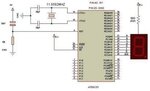
I am currently working on a project that requires an 8051 to increment/decrement a 7 seg display. I have built the circuit and tested it all. But i am having real problems when using ASM to display the right numbers on the display.

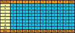
I am using a BCD (CD4511) chip connected to my display and when i checked it the numbers display 0-9 correctly. however when i tried the same thing using code i hit a 'wall'. Below is the code i have used to run through numbers 0-9:

Code:
org 0000h

main:	mov r0,#08h
        mov a,#00000001b      ;test all segments of disp
up:  	rr a
        mov P2,a
     	acall delay
       	djnz r0,up

again:  mov P2,#0000  ;'0'
    	acall delay
        mov P2,#0001   ;'1'
        acall delay
     	mov P2,#0010   ;'2'
        acall delay
     	mov P2,#0011   ;'3'
        acall delay
     	mov P2,#0100   ;'4'
     	acall delay
     	mov P2,#0101   ;'5'
    	acall delay
        mov P2,#0110   ;'6'
     	acall delay
     	mov P2,#0111   ;'7'
     	acall delay
     	mov P2,#1000   ;'8'
     	acall delay
     	mov P2,#1001   ;'9'
     	acall delay
       	sjmp again
        
delay:	mov r2,#100         ;delay subroutine
up3:	        mov r4,#100
up2:	        mov r3,#100
up1:	        djnz r3,up1
	        djnz r4,up2
	        djnz r2,up3
ret
I do not understand where i am making a mistake, and would appreciate any help that may be available.

Shar
 

Just add an END at the end of the code below the return. It is important while writing an assembly language code.
Regards,
Jerin. ;-)
 

Thanks for your quick response Jerin,

however that is still not working. The display should run through the numbers 0-9 but when i run the code (with END included), the only numbers being diplayed are:

4
0
8
0
1
0
in that order.
But when i tested the outputs using the logic gates on a breadboard it displayed 0-9 perfectly. Im just really confused.

Shar
 

there is another way of interfacing seven segment directly with 8051
here is the code

Code:
;SEVEN SEGMENT COMMON ANODE DISPLAY CONNECTED TO PORT2 
	ZERO 	EQU 0C0H
	ONE	EQU 0F9H
	TWO	EQU 0A4H
	THREE EQU 0B0H
	FOUR	EQU 99H
	FIVE	EQU 92H
	SIX	EQU 82H
	SEVEN	EQU 0F8H
	EIGHT	EQU 80H
	NINE	EQU 90H
	DOT 	EQU 7FH
	
	ORG 00H
	
		MOV P2,#00H
LOOP:	
		MOV P2,#ZERO
		CALL DELAYS
		MOV P2,#ONE
		CALL DELAYS

		MOV P2,#TWO
		CALL DELAYS

		MOV P2,#THREE
		CALL DELAYS

		MOV P2,#FOUR
		CALL DELAYS

		MOV P2,#FIVE
		CALL DELAYS

		MOV P2,#SIX
		CALL DELAYS

		MOV P2,#SEVEN
		CALL DELAYS

		MOV P2,#EIGHT
		CALL DELAYS

		MOV P2,#NINE
   	CALL DELAYS

   	MOV P2,#DOT
   	CALL DELAYS

   	AJMP LOOP
   	
DELAYS:	       	 ;1s DELAY
		MOV R5,#10
	D1:
		CALL DELAY
		DJNZ R5,D1
		RET
				
	DELAY:          ;100ms DELAY
		MOV R7,#200
	D2:								
		MOV R6,#100
	D3:	
		NOP
		NOP
		NOP
		DJNZ R6,D3
		DJNZ R7,D2	
		RET
END
i think your problem may be in connection between mcu and bcd to seven segment decoder pls check ,you are using four bit only try eight bit of port 2
 
Last edited:

at SHARMCN: the problme is tht u are writing " 0000" u shud write " 0000 0000 "
but before that u must ensure that ARE U USING COMMON ANODE or COMMON CATHODE configuration for 7-seg disp

after that u decide wat logic will be give for respective values (LEDs) to b turn on
hope this answers your query.....
 

Which display are you using i mean common anode or cathode? Did you simulate the code in PROTEUS? You want BCD numbers to be displayed rite?
Regards,
Jerin. ;-)
 

santoshaxl: Thank you for the code but that is still not working for me, it just displays 4 & 5 in a loop. I have tried it on a few different ADuC831 boards and am getting the same result. :???:

Bilal Sadiq: I am using a common cathode. and the reason i am using 4 bit binary is because my decoder chip(4511) is a 4 bit.

incomplete_jerin: I am using Aspire to simulate code.

Thank you all for your assistance with this matter
Shar :oops: :smile:
 

my code works for common anode and for common cathod you have to change port value
for microcontroller it is always better to work with common anode
you should know sinking vs sourcing ( current ) for microcontroller
 

why dint u just use transistor as a driver and connect it to the display... u can make truth table and give code accordingly
 

for single seven segment ( common anode display ) transistor is not needed we can directly connect seven segment to micro
you can use transistor that is optional just bulky and nothing
 

here is the circuit you don't need to use transistor (just bulky !)
truth table
 

Attachments

  • 7segcir-custom;size_425,250;brt_53.jpg
    7segcir-custom;size_425,250;brt_53.jpg
    17.6 KB · Views: 65
  • 7segt-custom;size_380,175.jpg
    7segt-custom;size_380,175.jpg
    29.6 KB · Views: 60

but if u use it without trans den it wod make the display very weak..ok make it and wen u want to see the display den turn off all the lights.
 

i think you are confused with electronics basics, the circuit that i have posted is working have you ever tried that circuit?
there are two types of display available common cathode and common anode the one i have used is common anode / when you are using common cathode may be your statement may be true otherwise using common anode there is no problem go for common anode fren
still you are confused pls post
 
Last edited:

Status
Not open for further replies.

Part and Inventory Search

Welcome to EDABoard.com

Sponsor

Back
Top