Continue to Site

Welcome to EDAboard.com

Welcome to our site! EDAboard.com is an international Electronics Discussion Forum focused on EDA software, circuits, schematics, books, theory, papers, asic, pld, 8051, DSP, Network, RF, Analog Design, PCB, Service Manuals... and a whole lot more! To participate you need to register. Registration is free. Click here to register now.

[SOLVED] RF 433Mhz module with PIC

Status
Not open for further replies.

vikas_verma

Junior Member level 1
Joined
Jun 30, 2010
Messages
19
Helped
3
Reputation
6
Reaction score
3
Trophy points
1,283
Location
Delhi
Activity points
1,393
hello everyone!
i'm working on my final year project that is a remote control car like a toy car but the difference is that i'm moving its front wheel like real one and it's speed too.
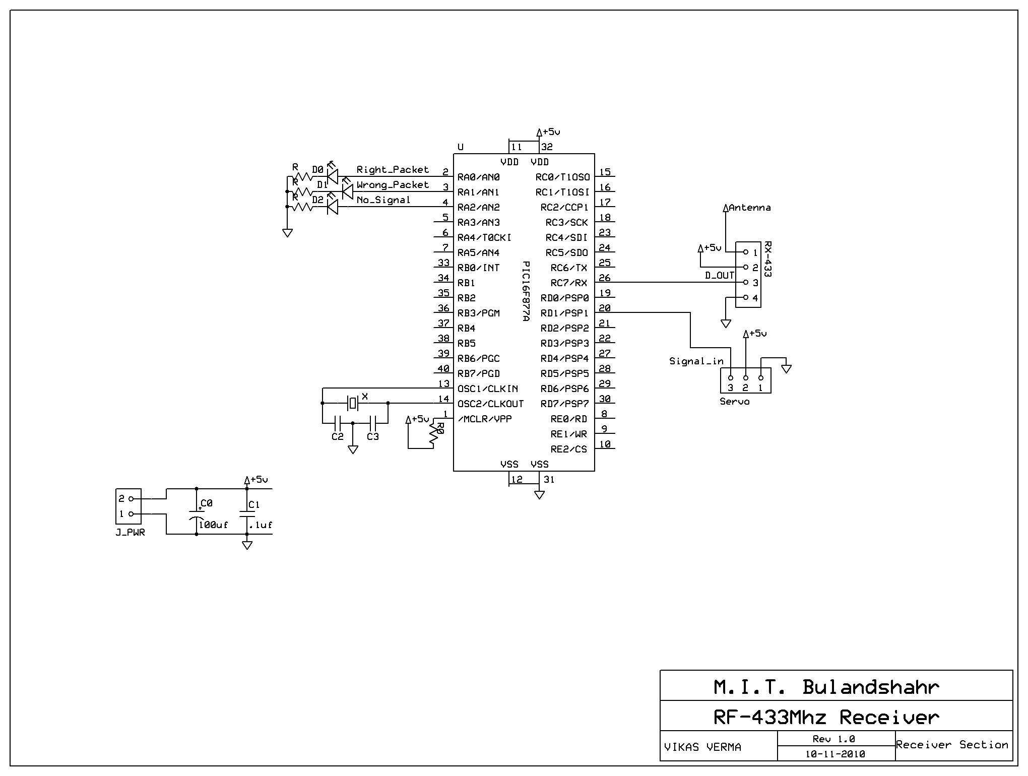
The problem i'm facing is in communication.i'm using simple 433Mhz rf modules,
PIC16f877A in transmitter and PIC16F628A as a receiver.problems are:

1. Receiving pic get blows when i connect it with RF receiver. (PICKIT2 doesn't detect it afterward ).
2. i want to send 2 bytes data so what should be the algorithm.
:-( please help me i've got few days to submit the project!
 

1. You have a serious wiring problem or a faulty power supply.
2. Check the transmitter buffer is empty by checking the flag then load the first byte. When the flag tells you the buffer has emptied, load the second byte. At the receiver, each byte arriving should set the UART receiver full flag to tell you when to read it.

Brian.
 

1. I'm using voltage regulator and battery as a power source so there is no
point of powering problem and RF receiver output is connected directly to
the PIC usart i/p pin.
2. yes, i'm testing the flag before writing to the TXREG register and using interrupt at receiver side. Data sending format is: 0x55 0xAA DATA 0x55 DATA 0xAA.
3. Is this RF module right choice for this kind of application?
 

Unless you post the circuit, no one can find out the problem.

If you are connecting motors to the same battery, then the reception will not be good.
Toy motors generate lot of noise.
 
  • Like
Reactions: shonet

    shonet

    Points: 2
    Helpful Answer Positive Rating
Unless you post the circuit, no one can find out the problem.

If you are connecting motors to the same battery, then the reception will not be good.
Toy motors generate lot of noise.

sir my circuit is on breadboard and not connected to any motor now.
all the ckt connections are okay. all the problem is in s/w section that is
i don't know what should be the time interval between a frame(bytes packet) of data in transmission.:cry:
actually i wanna know about the transmission and reception flow diagram or
something like that. help me soon!:roll:
 

There is no specific rules for time interval between a frame.

One more thing is the micro still got blowing whenever you connect the module?
 

You should also consider that simple RF modules may not carry the data in it's raw form. For reasons explained elsewhere on this forum, you may have to encode the data to be sure it can be decoded properly.
Damage to the PIC still suggest a wiring problem though.

Brian.
 

Hi,

Any schematics ???

What are your RF modules ?

How the receiver is connected to the PIC ?
 

Hi,

Any schematics ???

What are your RF modules ?

How the receiver is connected to the PIC ?

no schematic yet coz i'm changing the circuit continuously.

those simple and cheap ASK 433Mhz Modules.

okay now i've sorted out all the problems which i was facing by changing the
PIC16F628A to PIC 16F877A.

Now the prob is that when i connect the servo to the PIC, it starts to
reset even i've connected the 100µF and a disk cap. of .1uF parallel to
the PIC supply.
plz rply soon.
thank u in advance.
 

Sorry but if you don't post schematics nobody can really figure out what the problem is.

Give the schematic causing the problem and explain the problem even if you change it after that.

pic burnout is caused by inverting vdd and vss (the only time I've done that it was the result).
 

Sorry but if you don't post schematics nobody can really figure out what the problem is.

Give the schematic causing the problem and explain the problem even if you change it after that.

pic burnout is caused by inverting vdd and vss (the only time I've done that it was the result).
Here's the schematic :

now the problem is that when i connect servo, PIC starts to reset itself.
Power source is the ELNOVA 5amp power supply.
 

As i said earlier dont connect any type of motor to the same power supply which is powering the micro.

Give seperate power to the pic
 

Hi,

Schematic seems OK for me.
I've use servos on some of my projects with pic and I never had problem even with the same power source.
In one of them I use a 12F675 as a mixer between a RC receiver and the servos, powered by just a 4.8V ni-mh battery.
so...

May be ...

What's your config word (2007h) ?
What are your crystal and capacitors value for the oscillator ?
What are the pulses width you are sending to the servo? They've to be between 1 and 2 us. If not you can bring the servo out of his min/max position, in this case the motor consumption increase a lot ...

:)wooh! now everything is working properly by separating the power supply.
yess! i did it. thanks everyone.
 

Status
Not open for further replies.

Part and Inventory Search

Welcome to EDABoard.com

Sponsor

Back
Top