Continue to Site

Welcome to EDAboard.com

Welcome to our site! EDAboard.com is an international Electronics Discussion Forum focused on EDA software, circuits, schematics, books, theory, papers, asic, pld, 8051, DSP, Network, RF, Analog Design, PCB, Service Manuals... and a whole lot more! To participate you need to register. Registration is free. Click here to register now.

Explain this drive circuit?

Status
Not open for further replies.

ants

Full Member level 4
Joined
Feb 20, 2010
Messages
199
Helped
1
Reputation
2
Reaction score
0
Trophy points
1,296
Location
UK
Activity points
3,006
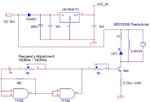
I'm trying to understand this circuit. It is a drive circuit for an ultrasonic atomiser and comes out of the atomisers datasheet. In particular I don't understand the purpose of the voltage regulator, or what Vcc at 5V is.

Thanks,

Ant.
 

Attachments

  • Untitled 1.jpg
    Untitled 1.jpg
    43.6 KB · Views: 87
  • 482943.pdf
    556.8 KB · Views: 69

The regulator is not shown as connected to anything but the 74132 needs a stable 5V supply for it to work so I guess that's what it's there for. It almost certainly provides 5V to the VCC pin on the 74132.

Brian.
 
  • Like
Reactions: ants

    ants

    Points: 2
    Helpful Answer Positive Rating
The circuit uses a TTL 74132 schmitt trigger as oscillator, TTL logic needs a 5V supply. The output stage is powered by 12V.
 
  • Like
Reactions: ants

    ants

    Points: 2
    Helpful Answer Positive Rating
That makes sense. The atomiser will be fed with 12Vpp then. What would be a good guess for the required current or power of this atomiser? It is 10 ohms so with I=V/R ~ 0.4A. But the the inductor in parallel will set up resonance increasing that to something else?

Thanks,

Ant.
 

The voltage could be as high as 24 Vpp due to the inductor action, but it isn't because the driver is current limited. If the frequency is optimal tuned, the inductor + transducer will form a real 10 ohm load.
 
  • Like
Reactions: ants

    ants

    Points: 2
    Helpful Answer Positive Rating
I see. 12- 24Vpp is more like the voltage these usually work at. How do you know it is current limited?

Thanks,

Ant.
 

Because of the base and emitter resistor and limited drive voltage. To achieve 24 Vpp output into 10 ohm, the peak transistor current must be 2.4 A, but considering the maximum TTL output voltage, it hardly can't achieve more than about 1.5 A.
 
  • Like
Reactions: ants

    ants

    Points: 2
    Helpful Answer Positive Rating
Status
Not open for further replies.

Similar threads

Part and Inventory Search

Welcome to EDABoard.com

Sponsor

Back
Top