HamidDabiri
Newbie
Hello,
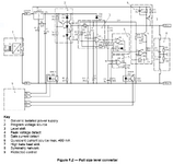
I am interested in knowing how this M-BUS Master circuit operates? Any section of it, especially the current source section.
I assume that when the required number of slaves are connected to the M-BUS lines, then the circuit fix the current and then the current source provides the currents for those slaves. When a slave sends a one, it would take around 15mA more and the current source cannot give the current , so the extra current is given by 36V which pass through the 50 Ohm sensing resistor, and from here it should switch on the opto-isolator diode and then a one is received.
Could you please look at the attached file and explain the operation of each section as much as possible.
Thank you and regards,
Hamid