fsmith
Newbie level 6
Gooday,
I am trying to implement a multiple input XNOR gate using the virtex II Pro unisim primitive BUTF. My VHDL code is as follows:
library IEEE;
use IEEE.std_logic_1164.all;
library unisim;
use unisim.vcomponents.all;
entity BUFT_XNOR is
port (
E_0, E_1, E_2, E_3 : in std_logic ;
enable : out std_logic );
end BUFT_XNOR ;
architecture XNOR_BUFT of BUFT_XNOR is
begin
DFF_Enable_0 : BUFT port map ( enable, E_0, E_3 );
DFF_Enable_1 : BUFT port map ( enable, E_1, E_0 );
DFF_Enable_2 : BUFT port map ( enable, E_2, E_1 );
DFF_Enable_3 : BUFT port map ( enable, E_3, E_2 );
PULLUP_Enable : PULLUP port map (enable);
PULLDOWN_Enable : PULLDOWN port map (enable);
end XNOR_BUFT;
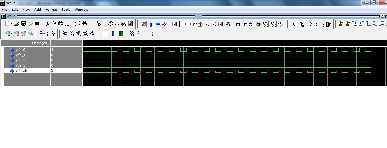
The code compiles fine, but when I simulate with Multisim, I get the output at shown in the attachment:
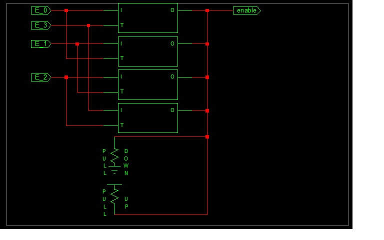
The Schematic:
Can anyone please tell me why I get the undefined output when one of the inputs is logic 1, and how to get the correct output.
Thank You.
F.
I am trying to implement a multiple input XNOR gate using the virtex II Pro unisim primitive BUTF. My VHDL code is as follows:
library IEEE;
use IEEE.std_logic_1164.all;
library unisim;
use unisim.vcomponents.all;
entity BUFT_XNOR is
port (
E_0, E_1, E_2, E_3 : in std_logic ;
enable : out std_logic );
end BUFT_XNOR ;
architecture XNOR_BUFT of BUFT_XNOR is
begin
DFF_Enable_0 : BUFT port map ( enable, E_0, E_3 );
DFF_Enable_1 : BUFT port map ( enable, E_1, E_0 );
DFF_Enable_2 : BUFT port map ( enable, E_2, E_1 );
DFF_Enable_3 : BUFT port map ( enable, E_3, E_2 );
PULLUP_Enable : PULLUP port map (enable);
PULLDOWN_Enable : PULLDOWN port map (enable);
end XNOR_BUFT;
The code compiles fine, but when I simulate with Multisim, I get the output at shown in the attachment:
The Schematic:
Can anyone please tell me why I get the undefined output when one of the inputs is logic 1, and how to get the correct output.
Thank You.
F.