Continue to Site

Welcome to EDAboard.com

Welcome to our site! EDAboard.com is an international Electronics Discussion Forum focused on EDA software, circuits, schematics, books, theory, papers, asic, pld, 8051, DSP, Network, RF, Analog Design, PCB, Service Manuals... and a whole lot more! To participate you need to register. Registration is free. Click here to register now.

Questions about CMOS cross-coupled crystal oscillator

Status
Not open for further replies.

Elektrix

Newbie level 4
Joined
Apr 13, 2010
Messages
5
Helped
0
Reputation
0
Reaction score
0
Trophy points
1,281
Activity points
1,331
Hi,

I'm trying to design a cross-coupled oscillator with a crystal attached to it with resonance freq of 5MHz.
I used the papers attached and the following threads:


But I still have a few questions:

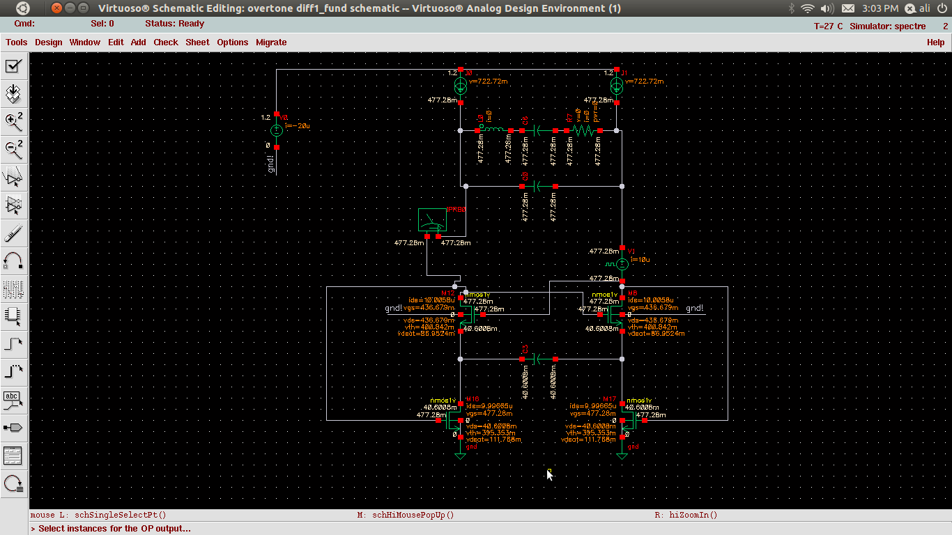
When I simulate the attached circuit I get a stable output oscillation (f = 5.05MHz) after some time.

But how can I be sure that the oscillator is working in 'crystal' mode and not relaxation mode? Because if I leave out the crystal, I still get an oscillation but with a slightly higher freq (5.71MHz).

I just chose the values for the source capacitor, the 2 resistors for matching de Vdd, and de RC values for biasing the tail current sources.

Is there anyone who can give me a guideline/explanation on how to choose the value of de top R's, RC tail values and the bottom capacitor?

Thanks in advance
 

Can anyone answer these questions?

- R en C for the drain current sources are chosen to filter out the 5MHz swing
=> ?

- Cs : There is a max limit on the capacitor set by the relaxation mode and min limit set by the necessity to have negative resistance at 35MHz.
=> how can I simulate the negative resistance at 35MHz?

I'm sorry for the (for you guys probably) stupid questions, but I'm quite new to analog design.


actually it is not stupid at all , iam trying to get this ct working but in vain , i need somebody to help me , iam totally lost

can any one help me here ?
 

You should clarify, which circuit you are trying to get working.

The simulation circuit in the original post (cross-coupled_crystal_oscillator_1604.jpg) hasn't reasonable component values, neither for the load resistors nor the crystal model.
 

here is my ct,
it is 40MHz xtal with r=5.6 ohm , L=3.18mH, cm=4.5f, co=5p
i need a value for current , cs in ordet to be salved to the xtal
plz help me
 

It looks like you have a problem with the DC bias. Both low side transistors are in ohmic region.
 
thnx saro :D,
actually i want it to oscillate it at 3rd overtone , thus i need a resonance amplifier in fb loop
can u help me in this , or post me some papers dealing with relaxation cts for 3rd overtone xtals
deeply appreciated :)
 

Status
Not open for further replies.

Part and Inventory Search

Welcome to EDABoard.com

Sponsor

Back
Top