Sleepy81
Newbie level 3
Hi!
I have a 4 switches that I'm goin to connect to a USB joystick board. The USB board has +5V and ground connections, and emulate a button press on a joystick when the circuit is closed. Just wiring up the buttons to the board works fine, but I have a problem that i'm unsure of how to solve.
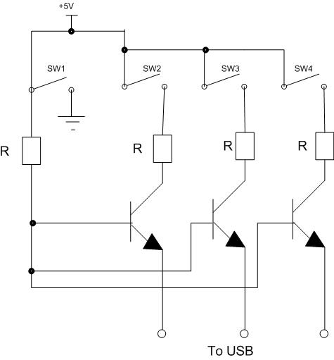
This is the how the 4 switches are wired now:
**broken link removed**
As you can see, what I want is for Switch 1 to break ground so that none of the other switches work until I have flipped Switch 1 on.
The problem I have is that I want Switch 1 to "enable" the other switches, but ALSO send a signal to the USB board. (requering it to have a +5V connection also.)
**broken link removed**
If I wire it up like above, I get a signal to my USB board also, but of course now Switch 1 does not break the ground circuit, so all the other buttons also work, regardless of Switch 1's position...
So is there a way that I could wire this setup so I both have Switch 1 able to break the ground for the other switches AND also have it send a signal (+5V) to the USB board?
I'm totaly unexperienced in these things, so I have no clue if its even possible.
I have a 4 switches that I'm goin to connect to a USB joystick board. The USB board has +5V and ground connections, and emulate a button press on a joystick when the circuit is closed. Just wiring up the buttons to the board works fine, but I have a problem that i'm unsure of how to solve.
This is the how the 4 switches are wired now:
**broken link removed**
As you can see, what I want is for Switch 1 to break ground so that none of the other switches work until I have flipped Switch 1 on.
The problem I have is that I want Switch 1 to "enable" the other switches, but ALSO send a signal to the USB board. (requering it to have a +5V connection also.)
**broken link removed**
If I wire it up like above, I get a signal to my USB board also, but of course now Switch 1 does not break the ground circuit, so all the other buttons also work, regardless of Switch 1's position...
So is there a way that I could wire this setup so I both have Switch 1 able to break the ground for the other switches AND also have it send a signal (+5V) to the USB board?
I'm totaly unexperienced in these things, so I have no clue if its even possible.
") ) to the circuit to make Switch 1 send a signal to the USB board AND break the ground to the other switches?
) to the circuit to make Switch 1 send a signal to the USB board AND break the ground to the other switches?