Continue to Site

Welcome to EDAboard.com

Welcome to our site! EDAboard.com is an international Electronics Discussion Forum focused on EDA software, circuits, schematics, books, theory, papers, asic, pld, 8051, DSP, Network, RF, Analog Design, PCB, Service Manuals... and a whole lot more! To participate you need to register. Registration is free. Click here to register now.

debugging AT89s52 -my whole circuit is not working

Status
Not open for further replies.

siva0182

Junior Member level 1
Joined
Jun 24, 2009
Messages
15
Helped
0
Reputation
0
Reaction score
0
Trophy points
1,281
Location
singapore
Activity points
1,424
at89s52 debug

I am a mechanical engineering student and having a tough time working with microcontrollers..PLease do help me solving this problem..

I have made the circuit for my AT89s52 in a PCB board and have written the .Hex file inside the controller.
The program recieves input thro serial port from the computer thro RS232 and pgm processes the input and sends suitable output to port 2..which then goes into a multiplexing circuit..
But right now my whole circuit is not working...I dont know where there is problem...
How can i measure the output of port 2.? And also how do i check if the serial port is transferring input ?(Baud rate bits etc wer same..but the for flow control type i am not sure which one i should use XOn/XoFF or None or hardware..

Any ways I am uploading my circuit diagram schematic and also the Rxd is connected to transmit pin of Rs232 and Txd is connected to Read pin of Rs232.
Also the output in the diagram is shown as port 1 but it is actually port 2.
I tried sending data thro hyperterminal..The pgms shows status as connected but the circuit is not working.

Please suggest debugging measures and methods.Also I want to verify my PCB circuit so is there any reference circuits for AT89S52.

(P.s:internal pgm has worked in previous projects.)
 

debugging at89s52

you can use Proteus software for simulation of microcontroller based circuits.
For software portion,you can use Keil or SDDC compilers.

You can use flow control NONE
 

at89s52 connection

What is the crystal frequency and what baud rate are you trying ?
 

at89s52 serial communication port circuit

I am using crystal frequency of 11.059200Mhz. (In the pgm soft copy it is rounded off to 12MHz )
Baud rates is 9600
 

Re: debugging AT89s52

siva0182 said:
In the pgm soft copy it is rounded off to 12MHz
Thats your problem! 11.0592 != 12MHz. You need to change the timer reload value considering 11.0592MHz crystal.

If using Timer-1 with SMOD=1, your reload value should be 0B8h and if SMOD=0, it should be 0DCh.
 

Re: debugging AT89s52

First of all, if 89S52 is programmed to use 11,0952MHz crystal for 9.6kbps then you have to use 11,0952MHz one as 12MHz will NOT work (unless you change the relevant Timer's reload values) ..

And second, I can't see any RS-232 line driver ..
Most common driver is the MAX232(or equivalent) ..
As an absolute minimum, you need two one-transistor inverters for RX and Tx lines ..

So, how did you connect the At89S52 to the serial port?

Rgds,
IanP
 

Re: debugging AT89s52

I am uploading the source code I have written inside the controller.
Actually the pgm was the same I used ina different similar set up and it worked.
Only the hardware has changed this time.

Regarding the Connection of serial port to RXD and TXD

I connected 16 WR to pin 2(RXD) of rs232 and 17 RD to pin 3(TXD) of RS232 directly.
There is no driver inbetween becasue i was told it would work.

I am not able to upload the .Txt or .C file.I will try the same in the next post

Added after 2 minutes:

I am attaching the source code here.ONly .doc or .pdf files get attached I did not know it before.
 

Re: debugging AT89s52

siva0182 said:
Regarding the Connection of serial port to RXD and TXD

I connected 16 WR to pin 2(RXD) of rs232 and 17 RD to pin 3(TXD) of RS232 directly.
There is no driver inbetween becasue i was told it would work.

Then you have also hardware problem ..
You need drivers (or at least inverters) on both lines (Rx and Tx) ..
See:

Rgds,
IanP
 

Re: debugging AT89s52

thanks alot.I will try to interface using this MAX232 driver and let you know the result later..

But so far bu direclty connecting Rs232 to microcontroller have I damaged the microcontoller?

Added after 2 hours 58 minutes:

I also Found another website where they use MAX232..
https://www.8051projects.net/serial-communication/introduction.php

BUt there is no extra capacitor as shown in the above recommended circuit ie between pin 15 and pin 2 .
IS it required or not?

Also let me know if there are any more errors in the hardware and software part so that i can correct

Added after 35 minutes:

i am referring to the capacitor between 5V and Ground.IS it required?
AS I found so in one of the links refferred and did not find in the another link i have quoted above.

Added after 8 minutes:

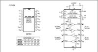
I did refer to MAx232 specificaiton sheet and id get the typical circuit diagram which i am attaching here.
The link referred to me first has the correct circuit diagram.Sorry for the confusion

BUt there is one more problem the polarity of the capacitor in pin 6 is not shown in the first diagram and in the specification sheet shows that -ve polarity is connected to pin 6 is that correct?

Added after 16 minutes:

another confusion is do i have to use WR/RD 16 and 17 for read and write or do ihave to use RXD and TXD 10 and 11 of the micro controller for serial communication?

Added after 11 minutes:

Again another inconsistency i observed was that the pin 2 and pin 3 of Rs232 connection to MAx232 differes in the link i quoted and in the one i was referred to.
However I think the one in mahesh wankhede site seems to be correct one just wanted to check it out.
 

Re: debugging AT89s52

about the max232, refer to datasheets sample application....for serial communication, you only need RX and TX pin... and i think you need to do some research and read some books..
 

Re: debugging AT89s52

I did refer ro max 232 and did the wiring and then tested it using an oscilloscope.
The one I got was MAX232 CPE I hope it is same as MAax232.
I have uploaded the specification circuit of the same.However I did find in other wesites like this one
https://www.8051projects.net/serial-communication/introduction.php

I got confused and some of my frends said that using ahighere capacitor is not a problem as it will tend to give more stability so i soldered five 10 micro farads.

but now i tried sending output from hyperterminal and measure the serial output from pin 9 (as 8 is connected to rs232 transmit pin 3 of DB9) using an oscilloscope probe and grounded the probe ground pin.
I sent AA55 etc thro hyperterminal..
But i dont see any output in the scope.
Could it be because of the capacitor value i have used?


Re: debugging AT89s52

you should first measure the output at TX pin..considering your new in programming, maybe your problem is on setting up the serial com. but if you have output, then it should be easy to determine your problem.
 

Re: debugging AT89s52

siva0182 said:
But so far bu direclty connecting Rs232 to microcontroller have I damaged the microcontoller?
Yes probably your microcontroller is damaged. RS232 operates at ±12V typical (±25V max) and microcontroller's pins are not meant to handle such high voltages.

10uF capacitor should work. I use it all the time with MAX232.
 

Re: debugging AT89s52

I am not using micrcontroller now..i am just using a Rs232 cable connected to the MAX232 and measure the output using oscilloscope probe.

THe data from Rs232 enters MAx232 thro R2in and leaves out thro R2out so i measure the oupput across R2out and gnd.
But I dont get any output.
I even tried another MAx232 but still it does not work...

Added after 2 hours 41 minutes:

I removed all hardware and just tested with only the rs232 cable.
I shorted pin 2 and 3 and sent data thro hyperterminal but the data ws not returned back.
What could be the reason?
I have only one com port and so i am specifying the correct COM port.
The bottom line of hyperterminal sys it is connected.
 

Re: debugging AT89s52

siva0182 said:
I removed all hardware and just tested with only the rs232 cable.
I shorted pin 2 and 3 and sent data thro hyperterminal but the data ws not returned back.
What could be the reason?
I have only one com port and so i am specifying the correct COM port.
The bottom line of hyperterminal sys it is connected.

Test your cable
 

Re: debugging AT89s52

I have used the same cable in the same port of the same computer to connect to a data acquistion unit..and it did communicate properly.
 

Re: debugging AT89s52

siva0182 said:
I have used the same cable in the same port of the same computer to connect to a data acquistion unit..and it did communicate properly.
Do the continuity check of the cable using a multimeter
 

Re: debugging AT89s52

Pin 5 as ground
Voltages at various pins

Voltage at end of cable -0.15 at pin 1
-11.45 at pins 4,7 ,9.

Voltage on PC port -11.3 at pin 3 and 4
-11.45 at pin 7.

The remianing pins have either 0 Volt or very small voltage like 0.15 V.

I have tested the working of the port and cable by connecting the same to a Data acquistion unit and the data was read correctly.

So There is problem in the way I am using hyperterminal or I am using the wrong pins while testing using hyperterminal.

Added after 3 hours 22 minutes:

My hyperterminal does not display any characters even when echo mode is on.
Any idea on why this could be?
 

Re: debugging AT89s52

siva0182 said:
So There is problem in the way I am using hyperterminal or I am using the wrong pins while testing using hyperterminal.
My hyperterminal does not display any characters even when echo mode is on.
Any idea on why this could be?
Have you selected the right COM port and opened it? Can you post the screenshot of hyperterminal?
 

Re: debugging AT89s52

I was able to solve the hyperterminal pgm when i used a different computer.I still dont know why my first computer did not respond..(even though it was able to communicate to a DAQ instrument).

And secondly my cable was cross wired and so my max232 output was not as expected so when i changed to a custom made straight cable the output of the max232 worked in aloop back test and as well in an oscilloscope.

BUt now the output of the max232 is fed to the micro controller circuit as posted earlier.(the first post..(which had a mistake of RXD and Txd pins ..whcih i have corrected now to the correct pin 10 and 11.)..but still the circuit does not work..
I have changed to a new microcontoller fearing the old one might have died.
IS ther any problem in my micrcontroller circuit.
How do I trouble shoot the output of port 2 8 pins?
 

Status
Not open for further replies.

Part and Inventory Search

Welcome to EDABoard.com

Sponsor

Back
Top