Continue to Site

Welcome to EDAboard.com

Welcome to our site! EDAboard.com is an international Electronics Discussion Forum focused on EDA software, circuits, schematics, books, theory, papers, asic, pld, 8051, DSP, Network, RF, Analog Design, PCB, Service Manuals... and a whole lot more! To participate you need to register. Registration is free. Click here to register now.

PLL with very high division ratio,spur problem

Status
Not open for further replies.

afz23

Full Member level 3
Joined
Nov 30, 2007
Messages
183
Helped
15
Reputation
30
Reaction score
14
Trophy points
1,298
Location
Bangalore
Activity points
2,758
very high loop bandwidth + pll

I am designing a programmable PLL based frequency synthesizer.

I am using intger-N PLL,right now only this PLL is available for project.

Fout=4000 to 4500 MHz

N= 32000 to 36000

Fcomp=125 KHz ( reference)

I designed loopfilter for BW=10KHz ,order 3 active type,but the
reference spurs are very high not at all acceptable.
I tried with order 4 also,it also didn't heped much.

Division ratio being very high (20logN>90dB) is also not
helping.

All you PLL experts please help me in solving this, and get rid of these
refrence spurs.
If any body has some literature which specifically deals with very high
division ratio,please give me that.
 

pe9763-01

High N values cause problems. Here are some possible solutions.

1. Create your output frequency from a mixing (addition or subtraction) of a fixed frequency crystal controlled and a PLL.

2. Another method that would be very expensive in your situation would be to generate a 10x frequency signal with the steps 10x what you need and then use a prescaler to divide by 10.

3. use 1 above with a DDS. This trades one set of problems for another set.
 

    afz23

    Points: 2
    Helpful Answer Positive Rating
opamp pll bias current reference spur loop filter

Well, physics is working against you. When you say that the loop bandwidth has to be 10 KHz, you are in effect saying that you want control loop open loop gain of 0 dB at 10 KHz, and approximately + 20 dB of gain at 1 KHz, -20 dB of gain at 100 KHz, etc etc.

The open loop gain is made up of the phase detector gain, the active loop filter gain at a specific frequency, the VCO tuning gain, and the "loss" of the divider. Since the divider is dividing by 36000, that effectively is a divider gain of 20 LOG(36000) = -91 dB.

So if you have an open loop gain of -20 dB at 100 KHz, and the divider has a gain of -91 dB, the (PD + OP AMP + VCO) gain has to be -20 -(-91)= + 71

That is a lot of gain after the phase detector acting on any spikes that are coming out of the phase detector.

So what can you do?

If there is some way to get the PD gain up without increasing the spike voltage, that would be a win.

If you can tweak the PD so that there is no small phase error spike occurring when locked. For instance, you might want to put a small + or - bias current into the op amp to compensate for PD offset or op amp bias.

You can design an elliptical notch filter at 125 KHz and 250 KHz. The trick is to make it very steep, so that it does not add much control loop phase at 10 KHz, which would make the control loop more unstable.

Anything you can do to reduce the divisor ratio would be smart. You might be stuck with one PLL chip part number, but are you stuck to only using ONE PLL circuit? You can make one synthesizer that works as an offset frequency to the 2nd PLL. If designed right, you can probably get the overall divisor ratio down.

There are a ton of other more comples ways. Like flatulent said, you could use a DDS to get the small frequency step size, and use only coarse steps in the PLL. Do realize that the DDS spurs and phase noise will be maginified in such a scheme, though.

There are plenty of cheap/good 622 MHz crystal and saw oscillators around now, for use in fiberoptic links. Take one of those, phase lock it to your crystal, triple it, and use it as an LO to downconvert the VCO before hitting the PLL. (or maybe the 622 MHz saw IS your reference, and you just divide it down to make the reference for the PLL chip).

There are plenty other variations of multi loop synthesizers, combinations of PLL's and comb generators, etc.

Good luck

Rich
 
Last edited by a moderator:

    afz23

    Points: 2
    Helpful Answer Positive Rating
spur problem

Thanks Rich for your detailed reply, dual loop
synthesizer is certainly a solution to this,but it
is expensive and complex.

What is your opinion ,if I decide to use a delta-sigma fractional-N
pll chip for this project,is it possible to get frequency steps of 125KHz
keeping Fcomp higher say 8.75MHz.

Will this scheme still has spur problem at 125KHz multiples or spur will
occur at Fcomp multiples? what should be loopBW in this case Fcomp/10 or
125KHz/10
 

suppressing fractional n spurs

if I decide to use a delta-sigma fractional-N

Yes, using a fractional PLL you can easily get 125kHz steps from 8.75MHz. In fact the higher the Fcomp the better as fractional spurious can be a potential problem at output frequencies that are close to multiples of Fcomp (and can be a problem elsewhere too : the key is to keep the loop bandwidth as narrow as possible for your application thereby giving maximum rejection of spurious). The higher Fcomp also greatly reduces the PLL division ratio giving lower overall phase noise.

Check out Analog devices or Peregrine semiconductor for such fractional PLL chips. For example the Peregrine part PE9763 works up to 50MHz Fcomp though you'll need a /2 prescaler at the VCO frequencies you're working at.
 

    afz23

    Points: 2
    Helpful Answer Positive Rating
cause for high reference spurs in pll

It is worth looking at. Fractional N offers a lot of promise, but for my applications I usually can not tolerate the additional spurs it produces.

Download the program AdsimPLL here:

http://forms.analog.com/form_pages/rfcomms/adisimpll.asp

It says it will predict fractional N spurs.
 

pe9704 charge pump

How high are the reference spurs in the original Integer-N design and how low do you need them? Are you sure that the problem isn't due to the bias current in the op-amp of the active loop filter?

By the way, you can simulate the effect of op amp bias current generating reference spurs using ADIsimPLL.

If the op amp bias current is low enough so that what you are seeing is the ref spurs from the chip, then there is still some scope to reduce them by adding complex poles to the loop filter. As an example, there are some loop filters in ADIsimPLL that have an inductor after the op-amp, I just tried a quick design for your parameters and you should be able to get about 20dB extra attenuation (compared to a simple 3rd order solution) at 125kHz Fpd with a 10kHz LBW.
 

    afz23

    Points: 2
    Helpful Answer Positive Rating
pll reference spur supresion

[Peregrine PE9763 fractional -N chip]

Yeah, I am also planning for this chip, this is a rad-hard chip
made from ultra CMOS technology (patented by peregrine),
this technology uses silicon on sapphire to achieve this performance.

Anybody have used this chip before, can somebody gives his/her view
about performance review of this chip.?

I have used peregrine PE9704 integer-N chip, excellent chip,
if any body wants any info on this chip,please contact.
Very Good chip if you are concerned about reliability and life
of your circuit.[/quote]
 

ad797 pll

Hi fred23,

Thanks for suggesting adisimpll to simulate reference spurs by
accounting opamp bias current.

I am practically observing op amp bias current 3-4mA.
And spurs are as high as -10Bc.

If I consider this bias current in adisimpll ,it gives spur level 60dBc,
Where as phase noise is -104dBc/Hz at Fpd.

What will be absolute spur level than? Phase noise (dBc)+spur level (dBc)


what best can be done in this case? Should I change my opamp to op27
for better noise performance? I am using general purpose LM118
righ now.

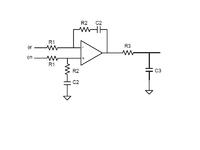
I am using the differential topology as the PLL chip provides up and down
outputs separately ,see figure.


spur in fractional pll

khanafzaal said:
Hi fred23,

Thanks for suggesting adisimpll to simulate reference spurs by
accounting opamp bias current.

I am practically observing op amp bias current 3-4mA.
And spurs are as high as -10Bc.

If I consider this bias current in adisimpll ,it gives spur level 60dBc,
Where as phase noise is -104dBc/Hz at Fpd.

What will be absolute spur level than? Phase noise (dBc)+spur level (dBc)


what best can be done in this case? Should I change my opamp to op27
for better noise performance? I am using general purpose LM118
righ now.

I am using the differential topology as the PLL chip provides up and down
outputs separately ,see figure.


Firstly I assumed that you had a charge pump pll chip. It's been a while since I played with the differential voltage output phase detectors, I suspect that theoretically the bias current is not important, but the offset current is. So yes, go to a device with lower bias/offset currents. The LM118 is a very noisy chip to use in a PLL loop filter.

Why don't you use one of the modern charge pump PLLs, you will probably get better phase noise and reference suppression (unless you are using one of the new Hittite chips, but I guess you aren't as you have such a noisy op amp).
 

    afz23

    Points: 2
    Helpful Answer Positive Rating
high division

Why don't you use one of the modern charge pump PLLs, you will probably get better phase noise and reference suppression

You'd be surprised.. best phase noise and spurious is often achieved using phase
detector outputs into a low noise op-amp (eg. OP37, THS4031, AD829, AD797 etc).
This can be for a few reasons, but amongst them are avoiding things like CP
mismatch (this can be a big contributor to fractional-n PLL noise/spurious),
improved PFD linearity (the 'PFD' dead-zone is sometimes actually caused by the
switch-on/off time of the charge pump not the PFD) and also the ability to drive VCOs with
a wide tuning voltage range.

Also if you have a VCO with a leaky tuneport it's better to use this kind of filter to
avoid excessive reference spurs you would get with a charge-pump.

The choice of Op-Amp though is key as it must be low noise (preferably
<5nV/rtHz), have low input offsets and have a reasonable bandwidth (much wider
than PLL loop bandwidth). OP27 would be a greatly improved choice over the
LM118 though if you have to consider PLL loop bandwidths wider than 50kHz the
faster OP37 would be better better.

Good Luck,

Martin
 

    afz23

    Points: 2
    Helpful Answer Positive Rating
Status
Not open for further replies.

Similar threads

Part and Inventory Search

Welcome to EDABoard.com

Sponsor

Back
Top