cipi-cips
Member level 4
Osciloscope
Hi!
I have some problems to fix first I need to build a device for 2 channel oscilloscope so it can show on display 4 signals ? OK so you have some 4 different signals, but on oscilloscope you can only see 2 of that 4 signals so there must be some kind of device where you can plug all 4 signals and than connect one on the channel (1 or 2 ) from oscilloscope to that device so oscilloscope can show all 4 signals something like this
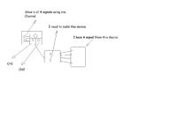
I know that Multiplexer must be used for this but dont know how??
Hi!
I have some problems to fix
first I need to build a device for 2 channel oscilloscope so it can show on display 4 signals ? OK so you have some 4 different signals, but on oscilloscope you can only see 2 of that 4 signals so there must be some kind of device where you can plug all 4 signals and than connect one on the channel (1 or 2 ) from oscilloscope to that device so oscilloscope can show all 4 signals something like this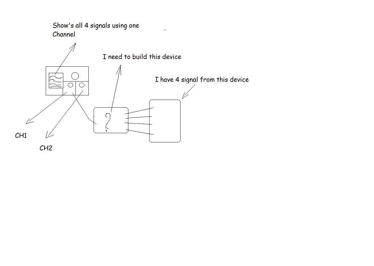
I know that Multiplexer must be used for this but dont know how??