Continue to Site

Welcome to EDAboard.com

Welcome to our site! EDAboard.com is an international Electronics Discussion Forum focused on EDA software, circuits, schematics, books, theory, papers, asic, pld, 8051, DSP, Network, RF, Analog Design, PCB, Service Manuals... and a whole lot more! To participate you need to register. Registration is free. Click here to register now.

Temperature coefficient of diode in Spice

Status
Not open for further replies.

Lucast85

Member level 3
Joined
Oct 19, 2009
Messages
62
Helped
4
Reputation
8
Reaction score
4
Trophy points
1,288
Location
Italy
Activity points
1,966
Dear all,
I'm trying to use a 3.0V zener diode (mmsz4683t1g) as a cheap "psu" for my microcontroller that could sink up to 2.3 uA of current @ 3.3V.
The board have to work over a temeprature range of -20 + 105°C.
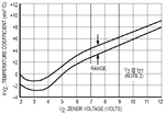
I know that the zener voltage depends from the diode current and from the temperature through the temperature coefficient. I read the datasheet and I expect a temperature coefficient of -2mV/K but this is not the result from the LTSpice simulation I performed @ Izt.
This is the result:
TC_zener.png
from which seems that the TC is -7.37mV/K. What's wrong?
Thanks to all!
 

The models cannot reflect his exact characteristics against actual measurements of a component.And these specifications vary pretty lot by lot.
The manufacturers give an average value for each but the best way is to measure.A precision current source ( a calibrator can be used ) is applied and diode reverse voltage can be measured against temperature in an laboratory oven.
 

I see a positive rather than negative TC in your simulation. -2 mv/K is the typical TC of a silicon diodes forward voltage.
 
I see a positive rather than negative TC in your simulation. -2 mv/K is the typical TC of a silicon diodes forward voltage.
Yes, Your're rigth! The the zener voltage increases as the temperature rises.
Here is a graph from Motorola (now called ON Semi):
I've a very similar graph but I expect to have a value close to -2 mV/°C, not a positive value (as correctly pointed out FvM) so far from the declared one.

Maybe this characteristic is not implemented in the zener diode model. Is it possible to understand this from the model itself?

Code:
.SUBCKT mmsz4683t1g 2 1
**************************************
*      Model Generated by MODPEX     *
*Copyright(c) Symmetry Design Systems*
*         All Rights Reserved        *
*    UNPUBLISHED LICENSED SOFTWARE   *
*   Contains Proprietary Information *
*      Which is The Property of      *
*     SYMMETRY OR ITS LICENSORS      *
*Commercial Use or Resale Restricted *
*   by Symmetry License Agreement    *
**************************************
* Model generated on May 10, 07
* MODEL FORMAT: PSpice
*     anode cathode
*node: 1      2
*    Forward Section
D1 2 1 MD1
.MODEL MD1 D IS=6.57933e-10 N=1.84949 XTI=1 RS=1
+ CJO=3e-10 TT=1e-08
*    Leakage Current
R 1 2 MDR 2.5e+06               
.MODEL MDR RES TC1=0 TC2=0
*    Breakdown
RZ 2 3 6.30533
IZG 4 3 4.8
R4 4 3 1000
D3 3 4 MD3
.MODEL MD3 D IS=2.5e-12 N=1.93475 XTI=0 EG=0.1
D2 5 4 MD2
.MODEL MD2 D IS=2.5e-12 N=10.5956 XTI=0 EG=0.1
EV1 1 5 6 0 1
IBV 0 6 0.001
RBV 6 0 MDRBV -153.607
.MODEL MDRBV RES TC1=0.0209365
*-- PSpice DIODE MODEL DEFAULT PARAMETER
*  VALUES ARE ASSUMED
*IS=1E-14 RS=0 N=1 TT=0 CJO=0
*VJ=1 M=0.5 EG=1.11 XTI=3 FC=0.5
*KF=0 AF=1 BV=inf IBV=1e-3 TNOM=27
.ENDS mmsz4683t1g

TY
 

Status
Not open for further replies.

Similar threads

Part and Inventory Search

Welcome to EDABoard.com

Sponsor

Back
Top