Continue to Site

Welcome to EDAboard.com

Welcome to our site! EDAboard.com is an international Electronics Discussion Forum focused on EDA software, circuits, schematics, books, theory, papers, asic, pld, 8051, DSP, Network, RF, Analog Design, PCB, Service Manuals... and a whole lot more! To participate you need to register. Registration is free. Click here to register now.

[SOLVED] Moved]: RE: differential loss cadence

Status
Not open for further replies.

kenambo

Full Member level 6
Joined
Feb 26, 2012
Messages
393
Helped
52
Reputation
104
Reaction score
48
Trophy points
1,308
Location
India
Activity points
3,859
Hi All,

I was doing S-parameter simulation in cadence to find out the differential loss of a simple circuit. I know the simple formula for return loss Return Loss = (ZL-ZS)/(ZL+ZS).
For simple resistor circuits the hand calculation and the cadence simulation results are same. For the attached circuit I couldn't able to realize the capacitors and find the return loss. In the following circuit, cap value= 2pF and resistances are 50 Ohms each with 100 ohm Port across them.

I am getting a value of S11 = 299.717mV. But I couldn't get the same value through calculation. Please refer the attached image.
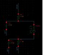

eda_sparam_new.jpg

Thanks.
 

S-parameter has no value "mV" at all.. I think you have to review your knowledge about them..
 

S-parameter has no value "mV" at all.. I think you have to review your knowledge about them..

Hi,

In cadence S11's magnitude is 299.717m , I assumed 1V(for understanding), so that I said it is 299.717mV. Anyway I correct this. This doesn't mean I should review my knowledge. Before commenting like this, you should understand what other person is trying to say. Watch your back, before commenting other's knowledge.
 

I was doing S-parameter simulation in cadence to find out the differential loss of a simple circuit.
In cadence S11's magnitude is 299.717m
They can not make sense at all.

Use correct terminology.

For the attached circuit I couldn't able to realize the capacitors and find the return loss.
In the following circuit, cap value= 2pF and resistances are 50 Ohms each with 100 ohm Port across them.
I am getting a value of S11 = 299.717mV.
But I couldn't get the same value through calculation.
Show me analysis frequecy or Netlist.

BTW, your S11 is not for differential mode, S11dd.
It is no more than for floating drive.
See https://www.edaboard.com/showthread.php?t=367048

Can you understand https://www.edaboard.com/showthread.php?t=365756#13 ?
 
Last edited:

They can not make sense at all.

Use correct terminology.

Show me analysis frequecy or Netlist.

BTW, your S11 is not for differential mode, S11dd.
It is no more than for floating drive.
See https://www.edaboard.com/showthread.php?t=367048

Can you understand https://www.edaboard.com/showthread.php?t=365756#13 ?


Hi,

I have gone through the attached threads. It is similar to this question but, in the attached snap there is only one port so S11 only available. And I assume this as return loss. In that case I assume Z0= 100 Ohms(Port Impedence).
so how to calculate Z1 so that i can substitute s11 = (Z0-Z1)/(Z0+Z1).

If there is no cap in the above circuit it is easy to say that Z1 = 50Ohm +50 Ohm = 100 Ohm and no loss. But now I have capacitance also. And I am sweeping frequency from 1Hz to 10GHz.

The S11 value at 1 GHz is 299.717m. Got my question?

Thanks
 

Simply you can not understand basic concept at all.
Can you understand "differential mode" ?

Hi,
See, If you know something.. please share it politely.
Simply you can not understand basic concept at all.?
. Can or cannot depends on myself only, So never say like this.

Coming to the point, We do this to measure the differential loss in my side and I know about the mode conversion and it needs more than 2 ports. In my design I have one port.. So simply I need to measure S11. I don't know whether it is differential.
So apart from saying "you dont know the basics...like these", try to understand what I am trying to measure from the attached circuit. and share your thoughts accordingly.

Thanks for the understanding.

Please Be polite on others. Everyone don't know everything. Thanks for understanding
 

I know about the mode conversion and it needs more than 2 ports.
I don't think you can understand basic concept.
Can or cannot depends on myself only, So never say like this.
Can you understand https://www.edaboard.com/showthread.php?t=365756#13 ?

In my design I have one port..
So simply I need to measure S11.
I don't know whether it is differential.
It is not differential.

Code:
gnuplot> pi=acos(-1)
gnuplot> f=1e9
gnuplot> w=2*pi*f
gnuplot> c=2e-12
gnuplot> pr 1/(w*c)
79.5774715459477
What is connected to "vbias" ?
What is connected to "gnd" ?

Show me netlist.
 
Last edited:

I assume AC impedance of nodes, gnd and vbias are zero.

Rp=2*50=100
Cp=2p/2=1p
omega=2*pi*1GHz
Zin=1/(1/Rp+j*omega*Cp)
Z0=100
S=(Zin-Z0)/(Zin+Z0)=-0.0898-j*0.2859
abs(S)=0.2997168
 
Hi,

Thanks . This is what I was looking for. I understood how cadence calculating this. Thank you so much for your time.
 

Last edited:

Status
Not open for further replies.

Similar threads

Part and Inventory Search

Welcome to EDABoard.com

Sponsor

Back
Top