catalin560
Junior Member level 2
Hello Forum! Noob engie here!
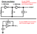
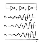
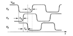
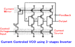
So I have this 3-stage ring oscillator of which I have to do a tran analysis and get a periodic wave that looks like its oscillating...however all my attempts have been far from what I'm trying to achieve... Check out these screenshots:


So I have this 3-stage ring oscillator of which I have to do a tran analysis and get a periodic wave that looks like its oscillating...however all my attempts have been far from what I'm trying to achieve... Check out these screenshots: