Continue to Site

Welcome to EDAboard.com

Welcome to our site! EDAboard.com is an international Electronics Discussion Forum focused on EDA software, circuits, schematics, books, theory, papers, asic, pld, 8051, DSP, Network, RF, Analog Design, PCB, Service Manuals... and a whole lot more! To participate you need to register. Registration is free. Click here to register now.

Any comments on the circuit? (RS232, RS422, MAX232)

Status
Not open for further replies.

tony_lth

Advanced Member level 5
Joined
Jul 28, 2010
Messages
2,088
Helped
377
Reputation
756
Reaction score
368
Trophy points
1,363
Location
Beijing
Activity points
12,635
Hi, ALL,
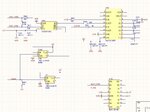
I designed a circuit, which can share RS422 and RS232 on the same pin.
Pls check the picture.
When "Control" is high, which has been pulled up to +5V.
IC400 Y =High, then U402 works properly, and U401 pin 13 F_TXD, i.e. RS232 TXD signal is converted to RS422 signals by U402. At the same time, U400 IN1 is "High", i.e. D1/S1 is OFF. So RS422_TXD+ pin is the TXD+ of RS422.

When "Control" is low, which should be linked to GND by GPIO, then U402 A/B are in high impedance, at the same time, U402 _RE is high, then U402 isn't in "receiver" status either.
But U400 D1/S1 is ON. So RS422_TXD+ pin is the TXD pin of RS232.
Finally, share the same pin for RS422 and RS232 signals.
Any comments?
Best,
Tony Liu
 

Attachments

  • 捕获.JPG
    捕获.JPG
    106.6 KB · Views: 353
  • 74HC1G126GW.pdf
    79.6 KB · Views: 95
  • DG411DY-E3 dg411-95218.pdf
    213.4 KB · Views: 99
  • MAX485MJA.pdf
    387.8 KB · Views: 87

Re: Any comments on the circuit?

I would be concerned about applying +/-12 (RS-232 levels) to the output of your RS-422 driver, it's only rated -8/+12.5. You don't show the supply voltages for the MAX232.
 
Re: Any comments on the circuit?

Hi, barry,
Could you make it clear about "applying +/- 12" to the RS422 driver"?
I don't understand what you mean.
And for MAX232, its supply voltage is +5V, which have been noted in the picture. I am confusion about your comment.
Best,
Tony Liu
 

Re: Any comments on the circuit?

Hi, barry,
Could you make it clear about "applying +/- 12" to the RS422 driver"?
I don't understand what you mean.
And for MAX232, its supply voltage is +5V, which have been noted in the picture. I am confusion about your comment.
Best,
Tony Liu
RS-232 operates at nominal +/-12 volt levels. These are generated internally by the MAX232 (not externally as I first thought). You need to verify what the actual levels coming out of the MAX232 are.
 

Re: Any comments on the circuit?

Hi, barry,
Thanks for your comment.
For MAX232, one side is TTL/CMOS, and the other side is RS232, as the picture.
So I think the level should be right.

Best,
Tony Liu

- - - Updated - - -

But I am not sure about linking U400/pin3 and U401/pin13 together, which linked a RS232 TXD signal to two IC's pins.
I noticed for MAX232, there is a 5K resistor to GND. If U400 has the same one, that would be 5K//5K=2.5K, that would cause 15V/2.5K=6mA to GND.
 

Attachments

  • MAX220-MAX249-67423.pdf
    445.5 KB · Views: 81
  • 捕获.JPG
    捕获.JPG
    87 KB · Views: 215

Re: Any comments on the circuit?

Ok, after closer inspection, I'm confused. When U402 driver is disabled, you've got RS-422TXD+ connected to RIN of the MAX232 through U400. And you've got R1OUT connected to the DISABLED input of U402. First problem is this means you've got RS-232 levels on the MAX485 I/O that can't handle RS-232 levels (I'm assuming you're driving RS-232 onto that line). Second problem is you've got a signal path that goes to a dead end.

When U402 driver is enabled, you've got U401 RIN floating (because U400 is open), and the driver input on U402 gets R1OUT (which is going to always be zero).

Maybe I'm misunderstanding your circuit?

What is it you're actually trying to do?
 
Re: Any comments on the circuit?

Hi, barry,
I intended to use a connector as a RS422 interface when "control" is high.
And use the connector as a RS232 interface when "control" is low, and use a different cable surely.

So how about this idea:
When "control" is high, power-off U400 and power-on U401/U402.
When "control" is low, power-on U400 and power-off U401/U402.

And I am confusion about your "when U402 driver is enabled" comment, MAX232 transfer TTL to RS232 level, that is R1IN and R1OUT function, why "R1OUT" is akways zero?

Best,
Tony Liu
 

Re: Any comments on the circuit?

I think you're confused, too. Rin is RS232, ROUT is TTL.
 

Hi, Barry,
1. I am not confused about MAX232, in the post #1 picture, R1IN is connected to F_TXD, which is RS232, and R1OUT is TTL. My design is right.

2. How about my idea to power on/off the ICs?

Best,
Tony Liu
 

Hi, Barry,
1. I am not confused about MAX232, in the post #1 picture, R1IN is connected to F_TXD, which is RS232, and R1OUT is TTL. My design is right.

2. How about my idea to power on/off the ICs?

Best,
Tony Liu

Maybe I'm missing something, but F_Txd is connected only to one side of your analog switch and RIN and nowhere else. Thus, the only time Rin will see a signal is when the switch is closed, connecting Ftxd to RS422+, right?
 
Hi,

Why don'tyou use ready to buy solutions? Like LTC2872.

Klaus
 
Hi, barry,
there is other circuit to drive RS232 TXD "F_TXD", which I don't show it.
Sorry to make some confusion.
Best,
Tony Liu
 

Hi, Klaus,
thanks for you comment.
I finally have done the SCH with LTC2872.
Pls comment if it is right.
Best,
Tony Liu
 

Attachments

  • 捕获.JPG
    捕获.JPG
    143.8 KB · Views: 170

Status
Not open for further replies.

Similar threads

Part and Inventory Search

Welcome to EDABoard.com

Sponsor

Back
Top