mahmood.n
Member level 5
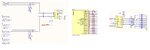
There is a Xilinx Spartan6 board with a schematic file which shows how the pins are connected to the outside.
Unfortunately, there is not enough information for some parts. According to the schematic and to reduce the IO
pin counts, there is a 74595 (serial to parallel register) to access the LEDs and a 74165 (parallel to serial register) to read the push buttons.
The schematic is not clear for me.
I have written a simple 5-bit counter That when I push a button (SW4), the counter must count up by one unit.
Problem is that I don't know how to assign the pins! For a Terasic Cyclone III board, it was easy to assign the pins.
According to the schemtic, SW4->P4 of 74165. That means the input of the parallel to serial (PISO) is 00010000.
In order to read that value, that register should be clocked five time to put the SW4 data on Q7 (DIP data). But what is that clock? The system clock has high speed. I have to use another button for clocking.
Is that right? Please let me know how to read the input. Then I will discuss on how to put the counter's value on the output pins.
Unfortunately, there is not enough information for some parts. According to the schematic and to reduce the IO
pin counts, there is a 74595 (serial to parallel register) to access the LEDs and a 74165 (parallel to serial register) to read the push buttons.
The schematic is not clear for me.
I have written a simple 5-bit counter That when I push a button (SW4), the counter must count up by one unit.
Code:
library ieee;
use ieee.std_logic_1164.all;
entity counter2 is
	port( clk, rst: in std_logic;
		  q: out integer range 0 to 31);
end;
architecture x of counter2 is
begin
	process( clk, rst )
		variable tmp: integer := 0;
	begin
		if ( rst = '1' ) then
			tmp := 0;
		elsif (clk'event and clk = '1') then
			tmp := tmp + 1;
			if ( tmp = 32 ) then
				tmp := 0;
			end if;
		end if;
		q <= tmp;
	end process;
end;
Problem is that I don't know how to assign the pins! For a Terasic Cyclone III board, it was easy to assign the pins.
According to the schemtic, SW4->P4 of 74165. That means the input of the parallel to serial (PISO) is 00010000.
In order to read that value, that register should be clocked five time to put the SW4 data on Q7 (DIP data). But what is that clock? The system clock has high speed. I have to use another button for clocking.
Is that right? Please let me know how to read the input. Then I will discuss on how to put the counter's value on the output pins.