Continue to Site

Welcome to EDAboard.com

Welcome to our site! EDAboard.com is an international Electronics Discussion Forum focused on EDA software, circuits, schematics, books, theory, papers, asic, pld, 8051, DSP, Network, RF, Analog Design, PCB, Service Manuals... and a whole lot more! To participate you need to register. Registration is free. Click here to register now.

SA602 colpitts oscillator help needed

Status
Not open for further replies.

atlantis7

Member level 2
Joined
Jan 11, 2007
Messages
43
Helped
0
Reputation
0
Reaction score
0
Trophy points
1,286
Activity points
1,745
Hi

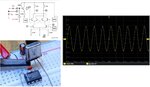
I need help with a SA602 design that should become a TX mixer in the end, however I'm stuck already with the oscillator. I need a 10.7 MHz oscillator and want it to be the basic colpitts topology with the crystal on pin 6 to ground, C1 between pins 6 and 7 and C2 on pin 7 to ground. The C1/C2 combination I calculated according to the "NE602 Primer" by Joseph Carr is 33p/100p, however I also tried 27p/270p, 47p/150p and 10p/22p, but whatever I do it doesn't seem to oscillate at all! What am I possibly doing wrong? At pin 6 I measure VCC and at pin 7 VCC minus about 0.5V and I have not connected any in- and outputs yet.

Kind regards
Martin
 

Is it asking too much to show the implemented schematic in this thread?
 
No, it sure isn't, here it comes:

mixer.jpg

The two coils are not tested yet and not connected at the moment.
 

What about the crystal specification ?? Some ICs accept particular crystal specifications otherwise they refuse to oscillate.Changing capacitance values does not help you because cap. values are defined for particular frequency by manufacturer.
 

I haven't found much about specific crystal specs for the SA602 but someone may know from experience. This crystal is fundamental/32pF/30Ohm, that's all I know. It's a generic type crystal from a distributor, 10.7 is not the most common frequency therefore I don't have another type to try.
 

I haven't found much about specific crystal specs for the SA602 but someone may know from experience. This crystal is fundamental/32pF/30Ohm, that's all I know. It's a generic type crystal from a distributor, 10.7 is not the most common frequency therefore I don't have another type to try.
If this will be a volume production, I suggest you to ask to manufacturer about the specifications of the crystal because even it works for a single sample of crystal, it may reject another sample.In order to insure that all device would work, the manufacturing standard should be satisfied.( I lived a bad experience so long time ago, 50% of the system returned back to us due to crystal compatibility problem)
 

BigBoss, thanks for this input, I'm sure you're absolutely right. However I don't plan on a volume production, therefore I just had to get what my distributor had and can't buy from a manufacturer directly.

What makes me suspicious is that I haven't read anywhere that any of the 602/612/605/615 etc series chips were particularly choosy about crystals...
OK,
There are other crystal configurations for that IC, have you ever tried them ?? Yours is not single configuration.Look at datasheet of this family.
 

Well... there's not really much more around for fundamental mode crystal oscillators.

This is from the datasheet:
oscillator1.jpg
Fundamental crystal mode is not mentioned at all...

This is from the above mentioned document "NE602 primer":
oscillator2.jpg
I did try version B with the trimmer cap in series with the crystal also.

And this is from AN1994 "Reviewing key areas when designing with the SA605":
oscillator3.jpg
Even though it is only recommended for overtone use I tried a Butler config (without the dc cap and the coil) as in the following schematic:
mixer2.jpg

At X I have some kind of oscillation but it's rather 2.5V DC with 0.5V ripple. The values chosen are from an article from Electronics World; maybe they're incorrect in this case but I don't know this topology at all and first need to get more info.
 

I find may designs using externally fed by discrete oscillators. Mostly, they are not depending on internal transistor for LO. Perhaps it helps resolve this issue and also internal interference due to oscillation .

sarma
vu3zmv
 

There should be no problem getting this to oscillate. I used a later version NE612 and a 10.7 MHz crystal filter connected as shown, and it worked without any problems. The probe is on the base (pin 6). On the emitter, the amplitude is a bit less.

Many years ago, I experimented a lot with the 612 and 614/5 making transceivers.

I also added a 22p trimmer in series with the crystal and could adjust it to exactly 10.7 MHz.

Tip: If you need a bit more amplitude, put a 22k resistor from pin 7 to GND.
 

Attachments

  • NE612_10_7.jpg
    NE612_10_7.jpg
    87.1 KB · Views: 166

Thanks to both of you for your new inputs!

E-design, thanks for trying this out and the additional tips, however I'm completely out of luck. Is my chip dead? I need to find out but I only have SMD ones and will also make a new pcb first at the same time. I'll let you know.
 

Finally it seems that these crystals are just crap for some reason. The new chip on a new pcb didn't change anything until I tried a 10.245 RX crystal and this one gave a result very much like E-design's. Unfortunately these are old stock crystals and I don't know their exact specs but they're nothing fancy I think. Now I need to find other 10.7 MHz crystals and the problem is I don't know what I'm looking for exactly...
 

Finally it seems that these crystals are just crap for some reason. The new chip on a new pcb didn't change anything until I tried a 10.245 RX crystal and this one gave a result very much like E-design's. Unfortunately these are old stock crystals and I don't know their exact specs but they're nothing fancy I think. Now I need to find other 10.7 MHz crystals and the problem is I don't know what I'm looking for exactly...
I said it above.IC Oscillators need-in general- particular Xtal specifications and these specifications are known/provided by either manufacturer or you can find them by cut-and-try method.
I have lived this in many times during years, therefore you'd better to ask these specifications to NXP and I believe they will answer you.
Instead of using low cost no-name crystals, you should use brand crystals.
 

It seems that I finally got that bloody ripper working, using 2x 39p, a 2-20p trimmer and the 22k resistor proposed by E-design. I'm not completely sure what made the difference in the end though.

Now on to the next challenge, maybe I should open a new thread for this but I first ask right here. On the in- and outputs I dropped the transformers that I originally intended to use, as long as they have to be developped and made manually with AL-values that seem to be nowhere close to reality this seemed never-ending. Therefore the input is now straight in and on the output I have a HPF (as described in the document by J. Carr mentioned earlier) because I want to select the sum and block the difference:

mixer.jpg

With the values from the schematic -3 dB is at about 11 MHz while the difference is 5.55 MHz and the sum 26.95. I also tried 330 nH and 100 p which should result in a higher -3 dB at about 18.5 MHz. In both cases I'm far from having the sum only at the output. See the screenshots (values as in the schematic):

Input:
TEK00001.gif

Oscillator:
TEK00002.gif

Output:
TEK00000.gif

After I captured these I also tried a version with a better impedance matching to the output with 330 nH, 150 pF, 1 uH but the waveform was only marginally better.

I'm not sure in which direction to do further investigation because the document does not go into much detail ("...[the filter] is designed such that its cutoff frequency is between the sum and difference frequencies") and other info on this output configuration is also scarce; is maybe 3rd order not enough or have I just not found the right cutoff yet?

If it was an IF output I'd consider using a wide enough ceramic IF filter.
 

Why OUT-B is floating ?? You should terminate it with a proper impedance for a convenient functionality.
 

You're right, it is flapping in the breeze there, however they do it like that in every AN I saw and also in many more circuits using this chip I looked at. Therefore I'm not too sure whether this is really necessary or even recommended with this particular chip. When I quickly tried with a 1k5 termination it seemed to me that the waveform did in fact look crappier than before.
 

Below is a BPF centered around 27 MHz, but good performance may be hard to achieve.
The value for C1 is only 2.2 pF which can easily be influenced by stray capacitance, which will degrade the specs of such a filter.

If you need a narrower filter, that means more stages. It becomes messy.
Maybe you need something like this:
http://www.amtsaw.com/brochure/saw/A02502.pdf

Do you require only a single output frequency or over a certain band?
 

Attachments

  • BPF.png
    BPF.png
    17.2 KB · Views: 158

E-design, many thanks for your design, unfortunately I wasn't able to test it due to the lack of the necessary inductors. And you're certainly right that it's better to use off-the-shelf filters, however if this thing is to be used as a TX mixer (with no further mixing or multiplying behind) there's now way around having it operate on the actual TX frequency...

Nevertheless I did still come a long way in the meantime because I discovered that the Norcal 40A transceiver does use the NE602 as exactly that:

40A.jpg

So I changed the values until I got a very nice simulated filter response:

filter.jpg
response.jpg
mixer2.jpg

Now I'm closer to a usable output than ever before, however right now the amplitude is jumping all over the place from about 400 mVPP to about 1200 mVPP. You can guess what it looks like from the screenshot but I wasn't able to capture the min and max at once:

TEK00000.jpg

What improvements can be done to refine and stabilize this?
 

Are you going to use this at a single fixed frequency?

Be careful about your RF input level. You want to stay below the 1 dB compression point.

Third-order intercept is typically -13 dBm (that is approximately +5 dBm output intercept because of the RF gain).The system designer must be cognizant of this large signal limitation. When designing LANs or other closed systems where transmission levels are high, and small-signal or signal-to-noise issues are not critical, the input to the SA602A should be appropriately scaled.
 

Attachments

  • comp1dB.png
    comp1dB.png
    14.9 KB · Views: 101

Status
Not open for further replies.

Similar threads

Part and Inventory Search

Welcome to EDABoard.com

Sponsor

Back
Top