Continue to Site

Welcome to EDAboard.com

Welcome to our site! EDAboard.com is an international Electronics Discussion Forum focused on EDA software, circuits, schematics, books, theory, papers, asic, pld, 8051, DSP, Network, RF, Analog Design, PCB, Service Manuals... and a whole lot more! To participate you need to register. Registration is free. Click here to register now.

how to do loading adjustment on the output of the transducer.

Status
Not open for further replies.

sys_eng

Full Member level 4
Joined
Aug 3, 2016
Messages
193
Helped
0
Reputation
2
Reaction score
1
Trophy points
18
Activity points
1,489
In the picture, blue color waveform is the output of the tranducer. when at the resonant frequency without the loading, the blue waveform is bigger amplitude than the yellow waveform,
when pressing the hand on the transducer it represents the loading (heavy loading) that change the output , the blue waveform drops to less than the yellow waveform.

How can I design the tranducer such that when heavy loading present, the blue waveform WON"T shift in amplitude and frequency?

loading.jpg
 

Very unclear what the actual application problem is. I also wonder how a waveform can "shift in frequency" although the frequency is set by a generator?

If the question applies somehow to ultrasonic power transducer operation, it's quite common to perform a load tuning. Simple generators (e.g. ultrasonic cleaners) achieve it by a self oscillating circuit with an operation frequency according to the actual resonance. A generator with independent oscillator might monitor output voltage and current and tune the oscillator frequency for maximum power transfer.

Here's diagram of no loading.No_loading.jpg

You compare the no loading with loading with the hand. Sorry, the phase got shifted, no the frequency.

actual application problem is real, like in water when there's changing water pressure that represent different loading condition that will shift the output amplitude and phase.

The environment is dynamic, the generator must able to cope with that.
Can you give an example of actual circuit doing the load tuning of what you talking about ? It must be involve some type of feedback system, right?

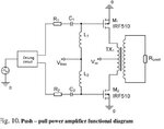
What about using push-pull with transformer at the generator to take of different loading on the transducer like this?

transformer.jpg
 

You can e.g. measure the current phase shift und use it to move the generator frequency up or down.
 

You can e.g. measure the current phase shift und use it to move the generator frequency up or down.

You cannot shift the frequency. If original spec is 20kHz, and that's the best frequency works with the substance. You shifted the frequency, then that's no longer the best one for the substance you work with.
 

You cannot shift the frequency. If original spec is 20kHz, and that's the best frequency works with the substance. You shifted the frequency, then that's no longer the best one for the substance you work with.
That doesn't sound substantiated at all. We are talking about a small frequency shift of e.g. a few 100 Hz.

But anyway, to understand the impedance matching requirements, you need to measure the complex transducer impedance over frequency for different load cases.

If you want to keep the frequency for any real or imagined reason, you'll use variable (e.g. stepwise switched) matching capacitors and inductors, or just accept a certain mismatching. Simply your decision.

do you have a specific circuit for the automatic load tuning you talking about?
 

Status
Not open for further replies.

Part and Inventory Search

Welcome to EDABoard.com

Sponsor

Back
Top