Continue to Site

Welcome to EDAboard.com

Welcome to our site! EDAboard.com is an international Electronics Discussion Forum focused on EDA software, circuits, schematics, books, theory, papers, asic, pld, 8051, DSP, Network, RF, Analog Design, PCB, Service Manuals... and a whole lot more! To participate you need to register. Registration is free. Click here to register now.

Replacing regenerative detector in circuit

Status
Not open for further replies.

neazoi

Advanced Member level 6
Joined
Jan 5, 2008
Messages
4,122
Helped
13
Reputation
26
Reaction score
15
Trophy points
1,318
Location
Greece
Activity points
36,951
Hi,
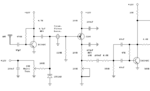
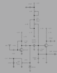
I would like to replace the regenerative detector in this circuit **broken link removed** (the one at the end of the pace), with the attached one. This is in order to cover more bands without changing any other component other than the resonator.

I have built it and it works. However, I am not sure I extract the audio from the right place. This is because, when I adjust the regeneration too low (pot close to the gnd), the output audio attenuates.
 

Attachments

  • a.PNG
    a.PNG
    16.4 KB · Views: 60

You can try this:
20170205_204319a.jpg

Its a variation on the detector in my experimental receiver. I have not tested this configuration and the regen voltage comes from a different source in my working version but you are welcome to try it and see what (if anything!) happens.

The problem I can see is the marked 1K resistor, in my version the parallel LC tuned circuit goes there so it presents a virtual short to DC. The resistor may create enough DC drop to stop the output FET from working properly as it should have 0V on it's gate I guess 1K as a compromise, making it lower helps the final stage but also drops the 'Q' of the resonator. You might find it works better if you replace it with a small choke (10uH ?).

No guarantees, it works well with LC but may not work at all with a resonator.

Brian.
 
  • Like
Reactions: neazoi

    neazoi

    Points: 2
    Helpful Answer Positive Rating
You can try this:
View attachment 135906

Its a variation on the detector in my experimental receiver. I have not tested this configuration and the regen voltage comes from a different source in my working version but you are welcome to try it and see what (if anything!) happens.

The problem I can see is the marked 1K resistor, in my version the parallel LC tuned circuit goes there so it presents a virtual short to DC. The resistor may create enough DC drop to stop the output FET from working properly as it should have 0V on it's gate I guess 1K as a compromise, making it lower helps the final stage but also drops the 'Q' of the resonator. You might find it works better if you replace it with a small choke (10uH ?).

No guarantees, it works well with LC but may not work at all with a resonator.

Brian.

Thanks for the excellent looking detector Brian, I will have a look at it, more complex though than my single oscillator.
I have noticed something and correct me if I am wrong.
In order to set the opposite sideband out of puff (and so detecting only USB), the regeneration must be smooth. That means two things:
1. You should be able to move the regen potentiometer quite a lot withing the "edge" of the oscillation, so you have better control over it.
2. The oscillator must be able to output very low levels at it's beginning of oscillation, and then gradually the output level must increase as you increase the regeneration.
3. Maybe the high Q of the crystal/ceramic resonator plays a role on this, I do not know.

Based on these assumptions I replaced the original detector with my FET version, because this is able to oscillate at all bands from 160m-10m. I did this so I can have an all-band RX by only changing the ceramic resonator. Of course I do not have a ceramic resonator for all bands, but I have tested the thing with crystals in the higher bands, which worked, but lost the number 2 point I described earlier, so I could not receive USB at these higher bands but only DSB.

I do not want to loose the "single signal reception" feature, can your version achieve that?
 

1. The regeneration on the prototype is very easy to control. The base voltage from the potentiometer can be adjusted by adding fixed resistors in series with the track ends if necessary, in my version its comes from a DAC so the pot doesn't exist. Maximum regeneration occurs when the base is at lowest voltage.

2. That works too, in fact one of the better points of the circuit is it doesn't 'latch', the threshold of oscillation is well defined as it enters and leaves the critical point.

3. As I said, the original uses an LC tuned circuit so I'm not even sure it will work with a resonator at all. The problem is the second FET, to operate properly it has to work at gate cut-off voltage which it achieves by using a high value source resistor and low resistance from the gate to ground. The inductor in the tuned circuit normally ensures the gate is DC grounded so that conditionis met. Obviously though, if you ground the output of the resonator it will never work so a compromise has to be met between loading the resonator and keeping the FET happy. A choke may work but make sure it's self resonance is well away from the frequencies you want to receive on.

One point I should have mentioned - it needs a high impedance load (>50K) at the audio output or the level will be very low. A single stage BJT amplifier should be adequate.

The prototype is working across the MW broadcast band at the moment and it receives well with no antenna and only an air-cored tuning coil. The regen control allows the bandwidth to be reduced to the point where the audio sounds 'down a drain pipe' so it clearly narrows it down to just a few hundred Hz.

Can you see how it works?

Brian.
 
  • Like
Reactions: neazoi

    neazoi

    Points: 2
    Helpful Answer Positive Rating
The regen control allows the bandwidth to be reduced to the point where the audio sounds 'down a drain pipe' so it clearly narrows it down to just a few hundred Hz.
Brian.
This is very interesting for an LC circuit. That much narrow bandwidth, could mean that it would be able to reject the opposite sideband, which is desirable for SSB/CW in my case.
When does this narrowing of the bandwidth happens in your case, when the oscillator level is set too high?
Is it prone to audio oscillation at this point?

I want to try my detector using an LC circuit instead of the resonator, because I am not convinced if the rejection of the opposite sideband, has to do with the high Q of the ceramic resonator, or the smooth regeneration control.
Do you think that it would be stable enough if I use good cores (eg. T68-5, T68-6 or better T68-7) and NP0 in parallel (or in series, to block DC), to replace the ceramic resonator?

I do not only consider frequency stability, but also frequency pulling when adjusting the regeneration control. The ceramic resonator excibits very tiny pulling when adjusting the regeneration control. This allows to operate the RX as a direct conversion (DSB) one, throughout the whole band, without adjusting the regeneration at all. It is also much more convenient than continuously having to adjust the regen control when changing frequency. Such things do matter for a convenient operation of an otherwise complex to tune regen.
 

Attachments

  • Capture.PNG
    Capture.PNG
    20.2 KB · Views: 44

This is very interesting for an LC circuit. That much narrow bandwidth, could mean that it would be able to reject the opposite sideband, which is desirable for SSB/CW in my case.
When does this narrowing of the bandwidth happens in your case, when the oscillator level is set too high?
Is it prone to audio oscillation at this point?

The narrowing is the classic peaking of the tuned circuit, it's 'Q' becomes very high so the bandwidth is reduced and audio sidebands chopped off. It happens just before the threshold of oscillation on normal AM broadcast stations but the Q should still be very high after oscillation has started so it will resolve SSB and CW. I'm not sure why you want to reject one sideband of an SSB signal when only one is transmitted anyway. You should be able to tune one side or the other of an SSB signal to resolve upper or lower sideband.

I see two potential problems in your schematic (post #5), one is the high value bias resistor, it makes the circuit more dependant on the feedback than the bias control and that tends to make the start and end points of oscillation move apart. You may have to advance the control to start regeneration then back it off quite a way to stop it again. The other is the resonator itself, it has built in capacitors (45pF) across it's input side and output side to ground, these reduce the tuning range and widen it's bandwidth when used in this application, it is really intended to be used as an alternative to a quartz crystal in a digital clock generator. You might try fitting a capacitor (100pF) in the ground leg but it might have other consequences.

You might be able to improve the regeneration by using a much lower bias resistor (~47K as a guess) and putting a controlled current source in the collector instead. It should have the same effect on gain and therefore regeneration but it will reduce the voltage effects on the resonator and hopefully pull its frequency less.

Brian.
 
  • Like
Reactions: neazoi

    neazoi

    Points: 2
    Helpful Answer Positive Rating
I'm not sure why you want to reject one sideband of an SSB signal when only one is transmitted anyway. You should be able to tune one side or the other of an SSB signal to resolve upper or lower sideband.

To reject the opposite sideband noise, but more importantly to reject the signals from other stations, that are in the opposite sideband, when you try to listen the other one. This cappens quite oftenly in crowded parts of the band. Also, to stop listenning twice the same station as you tune the dial. It is important, for all the reasons that single signal reception is important.

I see two potential problems in your schematic (post #5), one is the high value bias resistor, it makes the circuit more dependant on the feedback than the bias control and that tends to make the start and end points of oscillation move apart. You may have to advance the control to start regeneration then back it off quite a way to stop it again.

I have noticed this in other circuits, I know what you mean. No there is no such problem in this circuit.

The other is the resonator itself, it has built in capacitors (45pF) across it's input side and output side to ground, these reduce the tuning range and widen it's bandwidth when used in this application, it is really intended to be used as an alternative to a quartz crystal in a digital clock generator. You might try fitting a capacitor (100pF) in the ground leg but it might have other consequences.

I will try the capacitor you mention, although I am happy of the way the circuit works, but it would be interesting to see what will happen if I do so.
I will be even happier if the circuit could work with LC as well and achieve the same selectivity and stability, but I guess no one can tell this unless it is tried.
 

Status
Not open for further replies.

Part and Inventory Search

Welcome to EDABoard.com

Sponsor

Back
Top