Continue to Site

Welcome to EDAboard.com

Welcome to our site! EDAboard.com is an international Electronics Discussion Forum focused on EDA software, circuits, schematics, books, theory, papers, asic, pld, 8051, DSP, Network, RF, Analog Design, PCB, Service Manuals... and a whole lot more! To participate you need to register. Registration is free. Click here to register now.

Barkhausen Kurz oscillator question

Status
Not open for further replies.

neazoi

Advanced Member level 6
Joined
Jan 5, 2008
Messages
4,123
Helped
13
Reputation
26
Reaction score
15
Trophy points
1,318
Location
Greece
Activity points
36,955

Uf = 0 turns of the heater and stops operation. Perhaps you meaned something different?
 

Uf = 0 turns of the heater and stops operation. Perhaps you meaned something different?

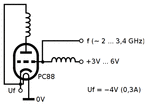
Yes. What I mean is to make Uf=0V Then make the other terminal of the filament (the one that connects to the cathode) = -4V
Also the anode will be -4V and it won't be connected to 0V as the schematic above shows.
However, the grid will still be fed with +6V (max)

So the heater will glow and the cathode and the anode will be at -4V, whereas the grid will be at +6V (max).

In other words, there will be a greater potential between the cathode/anode and the grid, and there is a ground point (0V) at Uf, as a reference for the output signal.

I believe this will increase the frequency, not the amplitude, but I am not sure. Wikipedia states "The frequency of oscillation depends on the spacing and potentials of the electrodes, and can be changed to a limited extent by altering the electrode voltages."
The increase in frequency, I believe will be caused by the higher potential difference that won't let the electrons approach too much the cathode and the anode, thus decreasing their path inside the tube.
 
Last edited:

I have doubts that PC88 will oscillate at 3GHz, even in this configuration. Did you actually measure the oscillation frequency?
The PC88 was designed for the old TV UHF tuners, and it has the maximum oscillation frequency at about 1.2 GHz.

http://www.electrojumble.org/Tuners01.pdf
 
  • Like
Reactions: neazoi

    neazoi

    Points: 2
    Helpful Answer Positive Rating
I have doubts that PC88 will oscillate at 3GHz, even in this configuration. Did you actually measure the oscillation frequency?
The PC88 was designed for the old TV UHF tuners, and it has the maximum oscillation frequency at about 1.2 GHz.

http://www.electrojumble.org/Tuners01.pdf

I did measure the frequency when I made this oscillator with the PC88. It was somewhere near 2GHz, even more. I do not remember at all now, as the circuit was made a year or so ago.

I remember I was impresed of how easily I could have a VCO at these frequencies, although the stability was not good and I bet the noise too.

What do you think of my idea in post #3? Will that work?
This "trick" increases the voltage difference between the grid and the other two electrodes,
 

Sad to say, I can remember all those tuner models!

I also think you are pushing your luck to get a PC88 much beyond 1GHz and in any case the PC86 was the one designed to be an oscillator. Those 'bottles' had a very short life expectancy, possibly becauase they were buried under so much shielding and ran red hot. If you have a salvaged one, treat it with suspicion, it has seem more than a few days use it will have deteriorated already.

Brian.
 
  • Like
Reactions: neazoi

    neazoi

    Points: 2
    Helpful Answer Positive Rating
Sad to say, I can remember all those tuner models!

I also think you are pushing your luck to get a PC88 much beyond 1GHz and in any case the PC86 was the one designed to be an oscillator. Those 'bottles' had a very short life expectancy, possibly becauase they were buried under so much shielding and ran red hot. If you have a salvaged one, treat it with suspicion, it has seem more than a few days use it will have deteriorated already.

Brian.

However, do you think the idea in post #3 will work?
 

It might work but I see a potential problem with making the grid more positive with respect to the cathode. It will behave like a diode and the extra voltage may force too much current to flow between the grid and cathode. Typically, when that happens you see a glow in the gap between them and the cathode coating gets damaged.

'Uf' is only the heater voltage "U" being a reference to Voltage and "f" for filament. It can be either polarity if it makes the construction easier. If you try passing signal current through the heater you should expect some instability and long delays before the frequency stabilizes.

Brian.

I do not think a so low voltage difference between the grid and the cathode will ruin the tube?
Instead of 6V difference in the original schematic, there will be a 10V difference in my version at maximum. These tubes are designed for much greater voltages.
In either ways the grid is more positive than the cathode anyway.

Here is the version I am talking about. Apart from other changes I have replaced the cored chokes with air cores, since at these frequencies they would not be core-based ones.
 

Attachments

  • osc.gif
    osc.gif
    8.9 KB · Views: 67
Last edited:

You would have to try it to be sure but don't forget they are designed for use with the grid more negative than the cathode, in other words with the 'diode' reverse biased.

Brian.
 

The original question has a trivial and advanced part.

The trivial part (calculating the positive grid voltage for the modified circuit) can be easily answered, I presume by yourself. Yes you get a +7..+10 V grid bias instead of original +3..+6V. Period.

The advanced part (what happens to the oscillation frequency and amplitude) can be only answered by experiment.

I presume that the linked circuit has been actually seen in operation. For an ideal drift tube and ideal external circuit (e.g. no parasitic L,C or transmission lines involved), there should be an f ~ √V relation. But a real PC88 has considerable construction size, capacitance and inductance. Also the external circuit won't be purely aperiodical. So it happens that empirical test reports are talking about oscillations stopping and restarting at certain voltage levels. Or the external circuit is designed as a resonator, so the frequency range is essentially fixed by design.
 

Yes, the answer is: build it, and measure it.
As was already stated, those tubes have very short life even in normal conditions, but when you push to their limits with 20mA-40mA grid current, they die even sooner.

https://upload.wikimedia.org/wikipedia/commons/3/33/Barkhausen_Kurz_PC86.jpg

This was the reason, when the first hybrid TV sets appears (valves+transistors), the first block that was replaced by transistors was the VHF/UHF tuner.
 
  • Like
Reactions: FvM

    FvM

    Points: 2
    Helpful Answer Positive Rating
Thanks for providing the schematic with gate current values. It clarifies why the positive gate bias must not be raised above +6V. Datasheet specified maximum cathode current is 13 mA, by the way.
 

Yes, the answer is: build it, and measure it.
As was already stated, those tubes have very short life even in normal conditions, but when you push to their limits with 20mA-40mA grid current, they die even sooner.

https://upload.wikimedia.org/wikipedia/commons/3/33/Barkhausen_Kurz_PC86.jpg

This was the reason, when the first hybrid TV sets appears (valves+transistors), the first block that was replaced by transistors was the VHF/UHF tuner.

Thank you for the useful info.

In the first unmodified version https://upload.wikimedia.org/wikipedia/commons/5/52/Barkhausen_Kurz_PC88.svg Why is the anode choke needed?
As far as I see it, electrons will bounce back and forth from the cathode to very close to the anode, but never "touching" each of them.
So why is the anode choke really needed?
 

Status
Not open for further replies.

Part and Inventory Search

Welcome to EDABoard.com

Sponsor

Back
Top