Debdut
Full Member level 3
I'm thinking of buying an antenna of this type - **broken link removed**
It will be at the output of a transmitter and the input of a receiver. The maximum distance between the transmitter & the receiver is 5 m.
I'm bad than a novice when it comes to electromagnetic transmission theory. So, please help me out or send me some references.
I want to know the following things -
1. What is the least power that the receiver section can detect and successfully amplify considering the LNA of the receiver has a gain of 5 to 10?
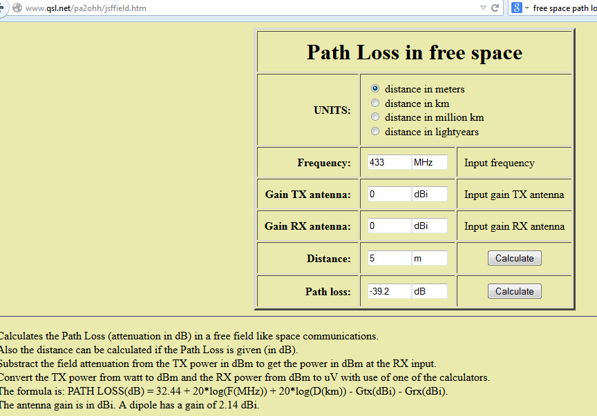
2. How can I calculate the power transmitted by the transmitted antenna considering least power received by the receiver antenna?
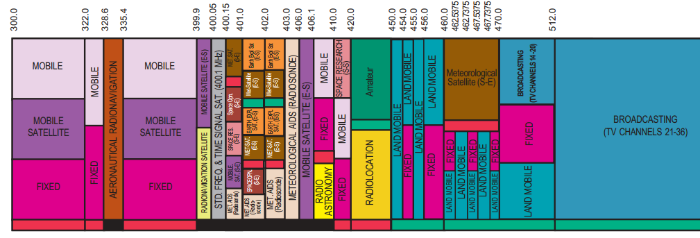
3. The output of the mixer is a sinusoid of frequency 400 MHz. Can the Power Amplifier before the antenna be class B or AB amplifier?
It will be at the output of a transmitter and the input of a receiver. The maximum distance between the transmitter & the receiver is 5 m.
I'm bad than a novice when it comes to electromagnetic transmission theory. So, please help me out or send me some references.
I want to know the following things -
1. What is the least power that the receiver section can detect and successfully amplify considering the LNA of the receiver has a gain of 5 to 10?
2. How can I calculate the power transmitted by the transmitted antenna considering least power received by the receiver antenna?
3. The output of the mixer is a sinusoid of frequency 400 MHz. Can the Power Amplifier before the antenna be class B or AB amplifier?