WirelessIce
Newbie level 2
Hello Everyone !
Well, I'm new in the field of RF. I have worked on few basic RF modules(like 433MHz Tx/Rx module, CC2500 Wireless Transceiver module) but these are way different from what I want to do now.
I wanted to explore more in this field and start searching for related stuff on google. It gave me so many links. Now the problem is I am confused where to start?:bang:
Objective:- What I am trying to do is to develop a product based on 2.4/5GHz for long distance communication with maximum throughput, following the standard communication protocols (802.11a/b/g/n) basically a Wlan(for example modules like ubiquity airgrid or rocketm5 or radwin).
I know there are SoC's like atheros wlan AR9280 but what about radio front end circuit? how to develop matching antenna? :drevil:
Help Needed - I need to develop this product from the start i.e. from PCB to complete product, so you can guide me on anything.
Please provide me with tutorials, books, papers, site links regarding the same. Any kind of help will be greatly appreciated.
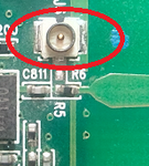
Do tell me what is this(red circled thing) in image? I have seen it in many RF devices, Earlier I considered it as an antenna but there was already an antenna in device.
**broken link removed**
Consider me a full newbie in the RF field, so you can give me tips on anything. Consider I don't know anything about antennas and how they work. Consider I don't know how to increase RF power using FEM.
p.s. - I have worked with many microcontrollers like atmel, pic, avr and ARM, so programming (if needed) will not be a problem.
Thank You!!
Last edited by a moderator:
