Continue to Site

Welcome to EDAboard.com

Welcome to our site! EDAboard.com is an international Electronics Discussion Forum focused on EDA software, circuits, schematics, books, theory, papers, asic, pld, 8051, DSP, Network, RF, Analog Design, PCB, Service Manuals... and a whole lot more! To participate you need to register. Registration is free. Click here to register now.

modified sine wave inverter loading problems

Status
Not open for further replies.

mohajernow

Newbie level 3
Joined
Jun 9, 2008
Messages
3
Helped
0
Reputation
0
Reaction score
0
Trophy points
1,281
Activity points
1,306
Hi every one

In the last week I built a modified sine wave inverter using pic16f628a but there is a about 50-70 voltage drop when I put a 160 watt load
According to the data sheet of the power mosfet it can deliver about 110 A so
why the mosfets do not provide the desired current to the load ?
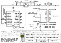
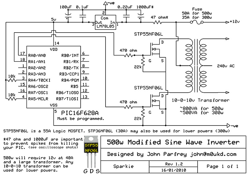
the following schematic is the basic of my design

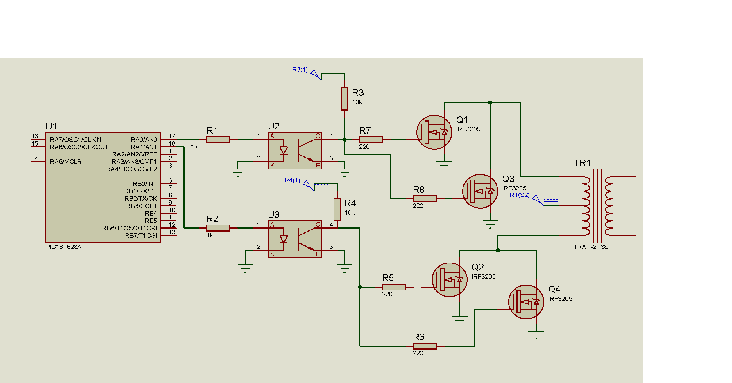
and the proteus file (attached image) is my modified circuit

Any help or suggestion will be appreciated
 

What makes you think the MOSFETs are the problem? It could be resistance in the battery, or in the transformer itself. Have you measured either of those?
 

What makes you think the MOSFETs are the problem? It could be resistance in the battery, or in the transformer itself. Have you measured either of those?
I measured the resistance of my transformer and it is short circuit ?
about the resistance of the battery how could it affect the rated power of the inverter ?
by the way the rated power of the transformer is 750 watt , it's primary is (9-0-9 or 12-0-12 ) and I use 9-0-9 to get the proper voltage at no load
 

I measured the resistance of my transformer and it is short circuit ?
It will probably be close to a short circuit (same with the battery), but it does have some resistance. A couple ohms of resistance is enough to explain your voltage droop.
about the resistance of the battery how could it affect the rated power of the inverter ?
Because the AC output will be proportional to the DC input, and resistance in the battery will cause the DC input voltage to drop.
 

Actually I measured the voltage battery and it was 12 volt but when I measured the voltage across the transformer I found it 11 volt , the drop was because of DMM which I used to monitor the output ampere .

There is another problem which I faced at no load there is about .8 A drawn from the battery how can I minimize it ?
Also I put 4 micro F capacitor at the output to smooth the output signal but it absorb about 3 A from the battery ,Do you think this is a normal situation (about 40 watt lost )?
 

I think someone here needs to go back to basics!

I'll try not to be a math teacher! You are steppng the voltage up by about 26 times. that means the primary current 'I', through the FETs is at least 26 times the current you are drawing at the output.
Voltage drop at the primary is I x R where R is the wiring resistance, FET resistance, battery ESR and transformer resistance. In relative terms quite a lot of resistance and hence quite a lot of voltage drop.

The current drawn from the battery is probably going to heat up the transformer. You are driving it with a square wave which is just about the least efficient waveform to use. Transformers like nice slowly rising and falling waveforms such as sine waves.

Putting a 4uF capacitor across the AC has two bad effects, firstly it has a reactance of about 800 Ohms so it draws about 0.3A, secondly, it detunes the transformer and distorts the waveform even more.

Brian.
 

Hello

I take it you're using the schematic made in Proteus, so I will comment on that. I will also assume you're not using PWM (even if you're calling it "sine-wave"). A 160W load means I = P/V = 160/12 ~ 13.3A max. The resitance "seen" by the MOSFETs will be R = V^2/P = 144/160 = 0.9 Ohms. Now, if you say the battery voltage drops by 1V at load, that means Rbatt = 1V/13.3A ~ 75mOhms. I don't know what ratio your transformer has, but I'll assume it's 9:230, as Brian predicted. Therefore the drop will be 26*1V ~ 26V. Add to this the transformer's resistance and the wire's and you'll get other volts that add up. Also, are the opto-coupler's transistors connected to the 12V or the 5V bus? I hope the 12V one, otherwise you won't drive the transistor to it's full (or close) Ron value. Given the very few details you gave, that's about as much as I can come up with.

Good luck,
Vlad
 

Hi,

I work on very similar push-pull converter project, did you consider to use dedicated chip like UC2846 or one of the newer versions.


regards
 

Status
Not open for further replies.

Similar threads

Part and Inventory Search

Welcome to EDABoard.com

Sponsor

Back
Top