Continue to Site

Welcome to EDAboard.com

Welcome to our site! EDAboard.com is an international Electronics Discussion Forum focused on EDA software, circuits, schematics, books, theory, papers, asic, pld, 8051, DSP, Network, RF, Analog Design, PCB, Service Manuals... and a whole lot more! To participate you need to register. Registration is free. Click here to register now.

How to select the highest output from 1 of the 4 sensors?

Status
Not open for further replies.

nafn

Newbie level 4
Joined
Feb 19, 2011
Messages
5
Helped
2
Reputation
4
Reaction score
2
Trophy points
1,283
Activity points
1,318
Hi all!
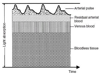
Please share your ideas with me. Here is my problem. I have 4 sensors which output four different values. The signals from these four outputs are combination of AC and DC signal and they are captured from a large portion area simultaneously.
My question is; Is there any method how can I select the highest value out of four outputs in analog domain? The reason I want to do this is to avoid complex signal processing technique later on.
Someone (from other forum I join) suggested me to use voltage follower with a diode in the feedback loop. But, this method is not that reliable based on the simulation results that I already carried out.

Please, do shed some lights upon this matter.
Many thanks in advance!
 

Please, do shed some lights upon this matter.
It's your turn, first. Without a definition of "highest ouput", the question can't be answered. A lot of options can be imagined:
- maximum (positive) instantaneous value
- maximum RMS level in a given period of time
- maxim avarage value in a given period of time
- etc.

Only the first one has a simple electronical representation, involving diodes and feedback amplifiers. You should be able to figure it out yourself.
 

If you first buffer each transducer so you have an output going to your metering circuits. You could normalize your gains at this point. Then four rectifier circuits, mean RMS or peak according to how you want to compare the signals. One way forward then could be to apply each of the signals to say the positive input of a comparator chip (four chips) and a slow frequency sawtooth to all the negative inputs of all the chips. Then ramping the sawtooth from say -10V to 0v would provide an output on the chip with the highest input. This could then stop the sawtooth and energise a switch that allows the highest signal through.
Problems are the signals time synchronous?, slowly moving DC?, How often do you want the circuit to check to see if its lselected the highest value?
Frank

Hi Frank!
The signals that I intend to measure are the photoplethysmography or PPG. Four PPG signals are captured simultaneously at different position of photodetectors. This signal contains AC and DC component. Please refer to the image attach.
From the simulation using optical software (TracePRO), the results show that there will be 1 photodetector which will receive the highest Irradiance value; which I expect will also have the highest voltage value after feed in thru the I-V converter.
SO, I'm thinking if there is any possible way on how to select that highest signal without changing its PPG characteristic (like the image below) so that it can be the only primary signal for further processing:idea:.
I hope this time my explanation is much clearer to you guys. Thank you in advance!:)

34_1298131481.jpg
* I don't own this picture
 

Status
Not open for further replies.

Part and Inventory Search

Welcome to EDABoard.com

Sponsor

Back
Top