Continue to Site

Welcome to EDAboard.com

Welcome to our site! EDAboard.com is an international Electronics Discussion Forum focused on EDA software, circuits, schematics, books, theory, papers, asic, pld, 8051, DSP, Network, RF, Analog Design, PCB, Service Manuals... and a whole lot more! To participate you need to register. Registration is free. Click here to register now.

Need advice on converting high frequency to low frequency

Status
Not open for further replies.

NicholasTok

Member level 1
Joined
Oct 2, 2007
Messages
36
Helped
0
Reputation
0
Reaction score
0
Trophy points
1,286
Activity points
1,587
I would need help on converting high frequency to low frequency and vise versa.

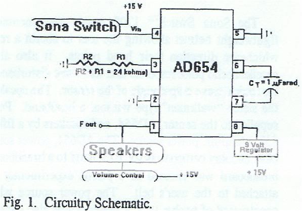
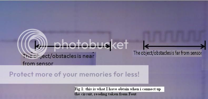
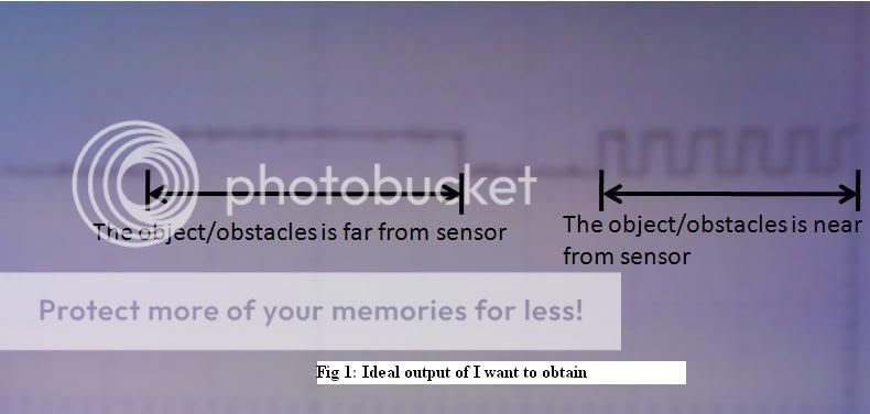
Currently I am doing a project on sensor, below is the schematic diagram. From my reading from Fout using the oscilloscope, the nearer an objects/obstacles the frequency increase and vise versa. May know what I should do/use to convert the high frequency to low frequency and vise versa.

or converting high frequency to low voltage and vise versa.

CircuitrySchematic.jpg

**broken link removed**

thanks in advance
Nicholas Tok
 

Re: Need advice on converting high frequency to low frequenc

NicholasTok,

Why do you want to: convert "high frequency to low frequency and vise versa"

If you want to measure/display/store (?) a voltage proportional to the distance"

Google: frequency to voltage converter

Ken
 

Converting freq? You want to altered the output of your sensor...very strange?

Anyway, what ever your purpose is, you can try to modulate the frequency by using nyquist or fourier transformation and bla bla bla yeah like that...

Your sensor topic is interesting, but your frequency conversion is not...in fact, it's strange. explain more detail.
 
Re: Need advice on converting high frequency to low frequenc

sorry, i think i had made some mistake on labeling the Fig 2

Fig 2 is actually what i wish to obtain, in fact my fout output is completely opposite of what I want.

I think i should make a repost so everyone will not get confuse.

below is 2 figures of waveform,
Fig 1: is what I have obtain from connecting up the circuit
Fig 2: is what I would like to obtain ideally.

OscilloscopeReadingg.jpg

Whatiwanttoobtain.jpg
 

Re: Need advice on converting high frequency to low frequenc

Hi,
Actually, you do not have to do anything, your sensor is working fine and apparantly giving out a frequency proportional to the distance. You can use a counter and do some scaling to display the distance directly.

I hope you are planning to measure pulse width. I am not sure if your Sonar switch has some jumper provision to select (1-x) arithmetic on the signal x, I mean when your signal is small, it should give the maximum output and minimum output when it is large.

Alternatively, you can change your circuit using a -5V supply, which I would not recommend, because your present circuit is really elegant with minimum components and functionally working OK.
Here is the required modifications incase you want to use - 5V supply.
Regards,
Laktronics
 
Re: Need advice on converting high frequency to low frequenc

bro laktronics,

thanks for your advice, before i continue with the connection may I know how you manage to calculate the value of the resistors use in this connection?

connection.jpg
 

Re: Need advice on converting high frequency to low frequenc

Hi,
Yes, I can do that. I hope you know about op-amps. Pin 3 of the IC is the -ve input of its internal opamp and pin 4 is its +ve input. As per data sheet, the IC produces its highest frequency, depending on the capacitor value, for 1mA current in the feedback transistor.
In your circuit, you have applied the sonar output to the positive input, pin 4. This will make pin 3 of the opamp to rise to the sonar voltage, since op-amp requires only a very small differential voltage across pins 3 and 4 to produce an output. Since you have connected a 4.8k resistor from pin 3 to ground, at 4.8V of the sonar output, a current of 4.8V ÷ 4.8k = 1mA will flow from pin 3 to ground, which will come from the collector-emitter of the feedback transistor. A good opamp does not take any current into its inputs. so, when your sonar produces 4.8V, you get maximum frequency and when sonar output is almost zero, the current through the transistor and hence the frequency generated by the transistor is the lowest. Now you wanted to reverse this condion, that is to generate 1mA current when the sonar output is minimum and viceversa.

In my modified circuit, the sonar connection is moved to the negative input of the opamp pin 3, through a 4.7k resistor. The negative input in this connection works as a virtual ground, since the +ve input is grounded through a 2.4k resistor. So, when sonar output is say zero, no current flows into pin 3 from sonar , but due to the -5V connection, a current of 1mA approximately (5V÷ 4.7k) flows to ground from pin 3. IC will now produce the highest frequency. Next, when the sonar output goes to say 5V, it produces a +ve current of 1mA into the virtual ground point, but since the same current is taken away by the -5V supply, the net curret supplied by the feedback transistor is zero, which means the IC will produce the lowest frequency.

BUT, HERE IS A CATCH, THE DESIGN ASSUMES THAT YOUR SONAR OUTPUT IMPEDANCE IS SMALL AND THAT IT CAN SUPPLY 1mA OF CURRENT AT 5V WITHOUT GETTING LOADED, YOU CAN CHECK IT BY CONNECTING A 4.7k RESISTOR TO GROUND IN YOUR PRESENT CIRCUIT FROM SONAR OUTPUT AT THE HIGHEST FREQUENCY TO SEE IF THERE IS CONSIDERABLE FALL IN OUTPUT VOLTAGEOF SONAR. IF IT IS THERE, YOU WILL NEED A BUFFER OPAMP TO BE PUT.

I still feel that your original circuit is the best and you only measure the frequency with a counter. Alternatively did you try if the sonar has any jumper position to provide (1-x) type output.
Regards,
Laktronics
 
Re: Need advice on converting high frequency to low frequenc

hello laktronics,

I am using LV-MaxSonar-EZ1 for my sonar sensor part, after i have measured the voltage output from the AN pin, I only have 1V when there is no object in front of the sensor.

I don't think that there is any jumper position to provide (1-x) type output for the sensor i am using. hmmm...

Thanks for helping me, please help me check this circuit it was design according to what you have said.


Regards,
Nicholas
 

Re: Need advice on converting high frequency to low frequenc

Hi Nicholas,
You need to connect one end of R3 of your circuit to -5V(Negative 5V) supply and not to ground. Do you have a -5V supply?
Regards,
Laktronics

Added after 43 minutes:

Hi Nicholas,
I am writing now to tell you some points I have noted after viewing LV Max sensor catalogue.
1. In your previous drawing, you have shown 15V supply being connected to LV Max, which you have corrected in your new drawing to Vcc. You should not apply more than 5V supply to LV Max.
2.Again as per the specification, it should provide around 2.5V analog output for objects placed at 250 inches away. You got only 1V output, It may be because on power on the auto calibration would not have taken place due to non presence of any object at its view distance.
In any case, your system should work if you can connect a negative 5V source to the R3 resistor in your modified circuit.
3.LV Max uses internally LM324 opamp and therefore no need to worry about analog output getting loaded. And it has no provision for 1-x operation.
Regards,
Laktronics.
 
Re: Need advice on converting high frequency to low frequenc

Hi laktronics,

I really appreciate your knowledgeable and kind help on solving my problem :D
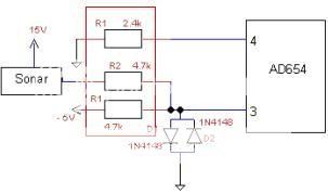
, this problem has really puzzling me for the last 2 days trying all sorts of method from adding an op-amp to reverse the signal from the AN pin which eventually spoil one of my sensor. I will go back to my workshop next Wednesday to test out the circuit and hope it works. Cheers :D 2 thumbs up for u.

Best Regards,
Nicholas Tok
 

Re: Need advice on converting high frequency to low frequenc

Hi Nicholas,
The vibrator motor has to be pulled up to its supply and not to ground, as in your original circuit where you have shown some speaker etc., pulled up to 15V. I did not take note of it yesterday as I was only looking at the changes I made at the input side.

Also since you are driving the motor using a square wave, you need to put some suppressor diode across it to protect your AD654 output driver.

The logic ground, pin 2 will carry the switching current from the motor and therefore better to connect separately to the -ve return of the 15V supply to which other grounds will also be connected. What is the specification of the motor, its current should be typically within 10mA to drive it directly from 654 IC.

Also, if your motor also can run from a 5V supply, you can eliminate the need for a 9V regulator and a 15V supply, though it may slightly affect the linearity of the frequency.
Regards
Laktronics

P.S. :You do not need to press help every time.
 

Re: Need advice on converting high frequency to low frequenc

Hi laktronics,

After reading the last reply, there is a lot of thing which I am very confuse on how it can be done? There will be 4 questions on this post, hope you don’t really mine sharing your knowledge with me, bow to you and really have to thank you for helping.

May I know how do you determine the types of suppressor diode to use since there is so many different types in the market, sorry about this. I really have no idea as I am very new to this suppressor diode before?

Can you show me example of schematic on how you actually connect up the suppressor diode across it to protect the AD654?

“The logic ground, pin 2 will carry the switching current from the motor and therefore better to connect separately to the -ve return of the 15V supply to which other grounds will also be connected.”

If I use 5V source throughout the whole circuit which can really save me a lot of time do I still have to do the quote above?

Best regards,
Nicholas Tok
 

Re: Need advice on converting high frequency to low frequenc

Hi Nicholas,
Sorry for the delay in replying.
Your new connection is ok provided your vibrator motor can work off 5V supply. You should connect Logic ground and 5V connection to motor, separately to your power supply connector, so that the current flowing through the motor does not go through the VCC and ground tracks of other circuits. Again you should put a DIP tanatulum capacitor of 10UF, 16V in parallel with a 0.1uF,16V ceramic capacitor across Vcc and ground pins of AD654 and LV Max to filter out any noise from the vibrator.

As regards, suppressor diode, you can connect a 5.6V, 1Watt Zener across the motor with its cathode connected to Vcc supply. Have you checked up the specifications of the motor, how much current it takes? Can it work from 5 Supply. If you can tell me the motor part number, I can check on the net.
I will send you the connection details for the vibrator portion after you confirm the motor specifications. At that time I will show you what I mean by separate connection to motor Vcc and logic ground.
Please note that you still need -5V supply for sonar connections.
Regards
Laktronics
 

Re: Need advice on converting high frequency to low frequenc

Hi laktronics,

For the motor wise, I will be getting 3-6v DC Motor, but I will only use 5v, as for the current consumption wise, I really have no idea as the motor has not been purchase as the website did not give any more in-dept specifications.
**broken link removed**

Best Regards,
Nicholas Tok
 

Re: Need advice on converting high frequency to low frequenc

Hi,
Here is the modified circuit diagram with suppressor diodes and recommended power supply filtering circuits. If you have any doubts, please let me know.
Regards,
Laktronics
 

Status
Not open for further replies.

Part and Inventory Search

Welcome to EDABoard.com

Sponsor

Back
Top