akj375
Newbie level 3
Hi All. I'm a graduate student and electronics is not my field, but I have to build an apparatus for my experiments and I'm very stuck. The device being operated What I’m ultimately hoping for is to draw a detailed circuit diagram so I can go out and buy the parts/pieces to build and test this setup. Here's the explanation what the circuit needs to do:
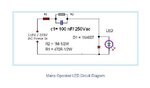
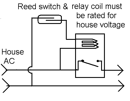
Please refer to the attached very crude diagram. The supply end of the circuits plugs into a regular wall socket for power. The power is routed through a relay switch which will operate devices on the receiving end when the circuit is closed. The power relay switch is normally open. In order to activate or close the power relay, a reed switch will be used. But here's the kicker... the reed switch has to be powered by the same power supply as the relay (i.e. from the wall outlet) rather than a battery. the reed switch would work similar to the ones mounted on security doors so that when a magnet is brought close to the reed switch it is activate (closed) and that triggers the relay to also close causing power to flow through the relay. The last thing is that there be a small LED after the relay switch that confirms that power is flowing through the relay, i.e. the receiving end of the circuit is energized. The final constraint is that all this be as compact as possible, so if using a solid state relay instead of a mechanical one would reduce size then that's what I would go with (suggestions please). And also the power relay has to be able to support up to 10amps - 15amp.
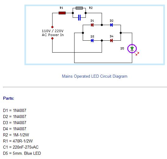
I don't know what (if anything) is needed to convert the AC power from the wall socket (120v) into DC power for the reed switch. Not sure if that's even necessary. I'm really circuit illiterate so I apologize. If you could give me as much
detail as you can on the parts to use (to buy) that that would be a huge help. It'd be great to know what to ask for when I go to shop for the parts. I really appreciate any help, especially diagrams, anyone can suggest. Please keep in mind that the more compact the set up the better because it has to be fit into a very small compartment. Thanks.
Please refer to the attached very crude diagram. The supply end of the circuits plugs into a regular wall socket for power. The power is routed through a relay switch which will operate devices on the receiving end when the circuit is closed. The power relay switch is normally open. In order to activate or close the power relay, a reed switch will be used. But here's the kicker... the reed switch has to be powered by the same power supply as the relay (i.e. from the wall outlet) rather than a battery. the reed switch would work similar to the ones mounted on security doors so that when a magnet is brought close to the reed switch it is activate (closed) and that triggers the relay to also close causing power to flow through the relay. The last thing is that there be a small LED after the relay switch that confirms that power is flowing through the relay, i.e. the receiving end of the circuit is energized. The final constraint is that all this be as compact as possible, so if using a solid state relay instead of a mechanical one would reduce size then that's what I would go with (suggestions please). And also the power relay has to be able to support up to 10amps - 15amp.
I don't know what (if anything) is needed to convert the AC power from the wall socket (120v) into DC power for the reed switch. Not sure if that's even necessary. I'm really circuit illiterate so I apologize. If you could give me as much
detail as you can on the parts to use (to buy) that that would be a huge help. It'd be great to know what to ask for when I go to shop for the parts. I really appreciate any help, especially diagrams, anyone can suggest. Please keep in mind that the more compact the set up the better because it has to be fit into a very small compartment. Thanks.
")