emerhidalgo
Newbie level 3
Good Morning Sir/Madam
I need some help with regards to this... Kindly help me please...
I made a counter program and circuit for the multi-coinslot with the following objectives
1. Count the pulse the output pulse of the coinslot
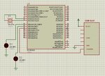
this was the schematic that I made which was now in an actual simulator

Here's the code written in MikroC Pro:
The code objective was to turn on a LED whenever the counter increments itself by using the trigger PORTB.F2
On my assumption it will turn ON PORTB.F2 at a very fast time interval so I wrote this code just to see if it will works but unfortunately it doesn't
Am I missing something important?
Here's the document of the multi-coinslot that I used.
**broken link removed**
Here's the part list
- PIC18F4620
- Multi-Coin Slot Model: 623
- Crystal Oscillator 20MGHz
I need some help with regards to this... Kindly help me please...
I made a counter program and circuit for the multi-coinslot with the following objectives
1. Count the pulse the output pulse of the coinslot
this was the schematic that I made which was now in an actual simulator

Here's the code written in MikroC Pro:
Code:
void main() {
  int counter = 0;
     //ADCON1 |= 1;
      //CMCON |= 7;
  TRISB = 0;
  PORTB = 0;
  while(1){
  if (PORTB.F2 == 1){
  counter++;
               if (counter==1){
               PORTB.F0 = 1;
               delay_ms(5000);
               }
               else if (counter>=2){
               PORTB.F1 = 1;
               delay_ms(5000);
               }
               delay_ms(5);

  }
}
}
The code objective was to turn on a LED whenever the counter increments itself by using the trigger PORTB.F2
On my assumption it will turn ON PORTB.F2 at a very fast time interval so I wrote this code just to see if it will works but unfortunately it doesn't
Am I missing something important?
Here's the document of the multi-coinslot that I used.
**broken link removed**
Here's the part list
- PIC18F4620
- Multi-Coin Slot Model: 623
- Crystal Oscillator 20MGHz
Attachments
Last edited: