Continue to Site

Welcome to EDAboard.com

Welcome to our site! EDAboard.com is an international Electronics Discussion Forum focused on EDA software, circuits, schematics, books, theory, papers, asic, pld, 8051, DSP, Network, RF, Analog Design, PCB, Service Manuals... and a whole lot more! To participate you need to register. Registration is free. Click here to register now.

Repeat on/off delay Timer

Status
Not open for further replies.
KerimF

Thanks for your input. I appreciate your help. But? I want to make this as small as i could.
With out using a microcontroller. And with the lease amount of ICs and passive parts.
Yes! If you may. ljcox is helping me to. I Think you guys
can give me what i'm looking for.

I went looking for a logic chip that has an ossillator on board.
The 4060 was all i could fine at the time of searching parts for this project.Since then.
I've done a search yesterday for parts and came across this part.
Its a 4521 24 stage counter.
**broken link removed**
I also came across this part.
http://www.datasheetcatalog.org/datasheet/philips/74HCT5555.pdf
Troughts on these parts. To make the circuit even smaller.

---------- Post added at 19:43 ---------- Previous post was at 19:22 ----------


ljcox
I understand this.

the 32.768 crystal is connected to the 4060 counter
at pins 11.10.
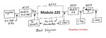
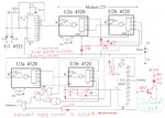
block 7 in your diagram i assume is the 4017 IC.
module 2, 60,60,24 is i think 2Hz 60secs 60secs 24Hs
Or they are 2Hz IC4060, IC4060, 24Hs. If i'm wrong which i assume i'am. Please Explain.Your diagram.
 

Thanks for the links, I had not considered these ICs.

Although either would do the job, the 74 HCT5555 has some complications & you don't need the extra speed offered by the 74HC series.

I'll draw a circuit later & post it this evening.

BTW the word is modulo not module.

Len
 

I did not manage to finish the circuit. Will do so tomorrow.

Here is the Block Diagram that it is based on.

I have also attached a gating paper that I wrote some years ago - based on one written by Norm McLeod.

Edit,
I have uploaded a new Block Diagram - it is simpler to realise.
 

Attachments

  • Logic Circuits.pdf
    173.3 KB · Views: 97
  • Block diagram 2.jpg
    Block diagram 2.jpg
    193.8 KB · Views: 98
Last edited:

The promised circuit & circuit description are attached.

I have not fully specified the gating arrangements. I need your input on this.

Do you want to use IC gates or diode/resistor (DR) gates?

The output gating will require a NOR gate IC, but the rest can be done with DR gates (or a combination of IC & DR gates) if you wish.

Each DR gate requires one resistor & one diode. So it is debatable whether IC gates will consume more PCB area. I'll leave it to you to let me know which way you want to jump.

SMD resistors & diodes would consume less area than "through the hole" ones.

I suggest that you build it in stages & test each stage as you go.

You can speed it up (for testing pusposes) by bypassing the Modulo 225 counter, ie. drive the Mod 24 counter with the 16 second pulses from U1 rather than the one hour pulses.
 

Attachments

  • Weekly Timer.gif
    Weekly Timer.gif
    39.5 KB · Views: 103
  • Circuit description.txt
    917 bytes · Views: 82
Last edited:

ljcox

First?
I need the completed circuit to operate at 3.6V 2mA or less thats why i chose cmos logic ICs.
Is the circuit going to function at those specs.
Second?
What FQ is the crystal components set at for the timing. Is it 32.768khz. Or is the FQ lower or higher.Explain?
What is the on/off pluse time rate is it 16secs (on) 16 secs (off)Explain?
Can i put an indicator led to verify this FOR TESTING.And where do i put it.
How am i going to know when the 4521 rearches 524288 on Q19 PIN 11.Can i use an indicator led at pin 11.
Three?
Put in the output gating,that will have the lease amount of space on a PCB and the lowest opreating current.
Four?
Why is there only one coupling capacitor on the positive rail and not on the negative rail on the 4521.
I know, i needed that on the 4060 when i used it.I used one (.1) ceramic disk on the POS/NEG rails.
five?
I will build each stage on a solderless breadboard for testing.Then use a surface mount pcb for final design.
Six?
On U4. WHEN will this be completely off. And will it stay off all day on sunday then start AGAIN the following Monday
starting at 8:30 again to repeat it again.
Seven?
Is the circuit in post #24 the final design. Or is there more to PUT the circuit.

There will more Questions to come as i construct the circuit.
 

I don't feel like answering your questions for 2 reasons:-
1. they are more like demands than requests.
2. you have shown no appreciation for the effort I have put in to designing it for you. I have many other things to do without this.

But I'll answer them anyway:-
1. Yes, but you will have to use CMOS gates not DR gates & you may need the power reducing resistors on U1 (see the spec)
2. Yes, see the block diagram in post #23. That diagram also indicates that 16 sec is the PERIOD of the waveform, ie. 8 sec high, 8 sec low. I'll post a diagram re the indicator LEDs later.
3. The least amount of PCB space may conflict with your desire for minimum current. So you will have to use ICs (rather than diode/resistor gates) for most of the gates. So you will need space for 3 gating ICs.
4. The 100 nF IS across the IC supply rails. The bottom end of the cap is connected to Gnd & the Vss pin (pin 8) is also connected to Gnd. BTW what you're calling the NEG rail is the Gnd or 0 Volt rail. It is not negative.
5. Good. That means that you can measure the supply current so we know if U1 will need the power reducing resistors.
6. That is the whole point of U4. It counts the days. Output 6 will be high on Sundays so the output will be low.
7. As I said in my previous post, I needed your input re the gating. So I'll now finalise the gating & re-post.
 

The Questions I asked.Were Not demands.I don't demand anything.From anyone.
Who would take the time to Help ME.This is why i join the forum.
How do i not show appreciation.
I posted links.I search for parts.To help make the circuit a smaller size.
There was no demands intended.

These questions are necsessary.So i could try and get a better understanding of the posted circuit.
And breadboarding the circuit..I'm a newbe at this stuff.Bare with me.I need to ask questions on what i don't understand.
Isn't that a part of learning this electronic sfuff.By asking what you don't know.

I go to school.So i wasn't home to get back to you.And they don't let us use our netbooks or go online during class.
That's why i couldn't get back to you on the gating.
As for the gating? If space is at minimum.Then you can go with the ICs for gating this will give minimum low current drain. Right?

Appreciate your time and help.
 
Last edited:

4521 Crystal  Set Up.PNG


Len

The circuit on page 8 in the 4521 datasheet the low current optional *R.
How do i calculate for these resistors in your circuit.
 

The Questions I asked.Were Not demands.I don't demand anything.From anyone.
Your text had a demanding tone. My wife read it & felt the same.
Who would take the time to Help ME.This is why i join the forum.
How do i not show appreciation. The occasional please & thank you would help.
I posted links.I search for parts.To help make the circuit a smaller size.
There was no demands intended. I did not think it was intentional, but I felt I should point out how it came across.

These questions are necsessary. I'm happy to answer the questions. I know you want to learn, so the questions are necessary. So i could try and get a better understanding of the posted circuit.
And breadboarding the circuit..I'm a newbe at this stuff.Bare with me.I need to ask questions on what i don't understand.
Isn't that a part of learning this electronic sfuff.By asking what you don't know. Exactly, I had no problem with the questions, it was just the tone of the English.

I go to school.So i wasn't home to get back to you.And they don't let us use our netbooks or go online during class.
That's why i couldn't get back to you on the gating.
As for the gating? If space is at minimum.Then you can go with the ICs for gating this will give minimum low current drain. Right? See below.

Appreciate your time and help.
The IC gates will require a very supply low current. DR gates would require a little more current.

As for the space, you would have to layout a draft PCB of both options to compare the areas.

If you wish, I can give you a circuit of both options so you can decide.

---------- Post added at 03:57 ---------- Previous post was at 03:50 ----------

View attachment 63654


Len

The circuit on page 8 in the 4521 datasheet the low current optional *R.
How do i calculate for these resistors in your circuit.
The data sheet does not indicate how to determine the value of these resistors.

However, if you look at the graph of current versus frequency, the power dissipation is about 30 mW at 40 kHz. So the current drawn from a 3.6 Volt supply will be about 30/3.6 = 8 uA. The other ICs will draw even less since they are counting at lower frequencies. So you should not need the resistors.

Edit.
I have extracted a graph of the frequency versus power dissipation from another 4521 spec that I have & it gives P = 100 uW at Vdd = 5 Volt.

So the current would be about 100/5 = 20 uA. However, since you are using 3.6 Volt, the current will be even less.
 

Attachments

  • 4521 extract.jpg
    4521 extract.jpg
    115.6 KB · Views: 96
Last edited:
  • Like
Reactions: Ebonic

    Ebonic

    Points: 2
    Helpful Answer Positive Rating
I have attached two drawings.

One that uses IC gates exclusively.

The other has one IC gate and several diode/resistor gates.

The diodes should be Schottky types such as the BAT41.

I have also shown how you can use LED's to monitor the counter outputs.

I have connected one (as an example) to the Sunday output of the 4017.

You can use any general purpose NPN transistors that you have on hand.

For example, BC546, BC547, BC548, BC549, 2N2222, 2N2222A, etc.

The LED's should be red or green as these have the lowest voltage drop.

You need this because you only have 3.6 volts to play with.

Please feel free to ask any questions you want.

Len
 

Attachments

  • Weekly Timer 1.gif
    Weekly Timer 1.gif
    45 KB · Views: 97
  • With DR gating.jpg
    With DR gating.jpg
    613.4 KB · Views: 97
  • Like
Reactions: Ebonic

    Ebonic

    Points: 2
    Helpful Answer Positive Rating
The LED's should be red or green as these have the lowest voltage drop.

In all 20mA LEDs I work with, I notice that the forward voltage of the red ones is about 2V and of the green ones 3.3V.
But perhaps, it is just me. For instance, yellow (and likely orange) LEDs are closer to the red ones.
After all, one can easily test an LED to measure its forward voltage for each driving current.

Kerim
I'm working from memory, so I must test the ones I have.

My recollection is that the green ones that I have are not much different to the red ones.

I'll test them later today and let you know.
 

Hi,

You may like to connect one red LED in series with a green one and a limiting resistor of 330 Ohm and drive them with 12V power supply. The current will be the same for the two LEDs; about 20mA. You can measure the LED forward voltage of each. I wait for your test result, perhaps there are different types for the green LED. Thanks

Kerim
 
  • Like
Reactions: Ebonic

    Ebonic

    Points: 2
    Helpful Answer Positive Rating
ljcox

I need to ask you about the block diagram in post # 23
I really need to understand this diagram before i begin
to construct the circuit. Please Help?

The 32.768khz crystal. Is that the FQ its resonating at
And the passive compoenets are calculated for this crystal.So it can work at that FQ.
What is the on/off pluse rate that the timing set at. Is it 16secs on and 16 secs off.
How long will it take to count to 524288 bits for the bistable flips to go High.
So would the total timing period be 32secs on/off. What is and should be the
FQ on the output of pin 11.

like to know what dose 225 meaning on the CD4520BE.
What will the FQ be on the the out modulo

thanks
 

Hi,

You may like to connect one red LED in series with a green one and a limiting resistor of 330 Ohm and drive them with 12V power supply. The current will be the same for the two LEDs; about 20mA. You can measure the LED forward voltage of each. I wait for your test result, perhaps there are different types for the green LED. Thanks

Kerim
Here are my results

LED tests

I Red Green
1.0 1.65 1.82
1.7 1.67 1.84
4.1 1.78 1.91
5.4 1.77 1.93
9.3 1.83 1.99
7.4 1.80 9.97
13.3 1.88 2.5
17.1 1.92 2.1
mA Volt Volt

So my Green LED must be different to yours.

Len
 
  • Like
Reactions: KerimF

    KerimF

    Points: 2
    Helpful Answer Positive Rating
ljcox

I need to ask you about the block diagram in post # 23
I really need to understand this diagram before i begin
to construct the circuit. Please Help?

The 32.768khz crystal. Is that the FQ its resonating at Yes
And the passive compoenets are calculated for this crystal.So it can work at that FQ. Yes
What is the on/off pluse rate that the timing set at. Is it 16secs on and 16 secs off. See below
How long will it take to count to 524288 bits for the bistable flips to go High.
So would the total timing period be 32secs on/off. What is and should be the
FQ on the output of pin 11.

like to know what dose 225 meaning on the CD4520BE. I assume you're refering to the "Modulo 225" above U2 on the circuit. See below.
What will the FQ be on the the out modulo I don't understand this question. Which counter are you asking about? The frequency is of little value in this case since the periods are very long. eg. The output of U1 has a period of 16 sec. This is 1/16 = 0.0625 Hz.

thanks

I forgot to post the circuit description that I had prepared. So I'll attach it below.

It will answer most of your questions.

The "Modulo 225" above U2 on the circuit means that I have designed the gating to rest the counters when the count reaches 225. Thus it counts fro 0 to 224 & then resets. So it is acting as a Modulo 225 counter. The same applies to U3. The gating resets the counters when the count reaches 24, hence it is a Modulo 24 counter.
 

Attachments

  • Circuit description.txt
    917 bytes · Views: 82
  • Like
Reactions: Ebonic

    Ebonic

    Points: 2
    Helpful Answer Positive Rating
Thank you Len.
It seems not all green LEDs need about 3.3 volts as mine...
Sorry for taking your time to check this difference for me.
Thanks.

Kerim
 

Thank you Len.
It seems not all green LEDs need about 3.3 volts as mine...
Sorry for taking your time to check this difference for me.
Thanks.

Kerim
You're welcome.

I was suprised the first time I measured one of these Green LEDs, I was expecting it to be higher.

I thought that the LED colour was determined by the energy gap (I can't remember the correct terminology) inside the semiconductor.

I have attached 2 graphs that I have on my computer - I don't remember the source of them now.

Len
 

Attachments

  • led voltage.jpg
    led voltage.jpg
    29.8 KB · Views: 92
  • Green25VA.JPG
    Green25VA.JPG
    89 KB · Views: 86
  • Like
Reactions: KerimF

    KerimF

    Points: 2
    Helpful Answer Positive Rating
Thank you Len,

I think, from now on, I should test the LED voltage everytime I got some from a new source :)
I wish my green and red LEDs have rather close voltages, since now each color needs different driver and sometimes different power supplies if in series.

Kerim
 

Thank you Len,

I think, from now on, I should test the LED voltage everytime I got some from a new source :)
I wish my green and red LEDs have rather close voltages, since now each color needs different driver and sometimes different power supplies if in series.

Kerim
Kermi
I don't understand why you need a different driver for different colours.

I just select the series resistor to suit the driver voltage & the LED voltage.

For example, see the resistor values I used in the attachment.

This is a PIC Programmer/Tester that was published in the Austrailan electronics magazine, Silicon Chip some years ago.

They specified all Red LEDs, but I wanted to have different colours to make it easier to identify the bits.

Len
 

Attachments

  • PIC Programmer-tester 18 Silicon Chip 2.gif
    PIC Programmer-tester 18 Silicon Chip 2.gif
    9.6 KB · Views: 97
  • Like
Reactions: KerimF

    KerimF

    Points: 2
    Helpful Answer Positive Rating
Status
Not open for further replies.

Part and Inventory Search

Welcome to EDABoard.com

Sponsor

Back
Top