Continue to Site

Welcome to EDAboard.com

Welcome to our site! EDAboard.com is an international Electronics Discussion Forum focused on EDA software, circuits, schematics, books, theory, papers, asic, pld, 8051, DSP, Network, RF, Analog Design, PCB, Service Manuals... and a whole lot more! To participate you need to register. Registration is free. Click here to register now.

Current Loop Doubt in Flyback Converter

Status
Not open for further replies.

nelsonys

Member level 4
Joined
May 23, 2011
Messages
77
Helped
8
Reputation
16
Reaction score
8
Trophy points
1,288
Activity points
2,034
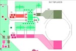
Please refer to the attachment. Sorry for the low quality image.

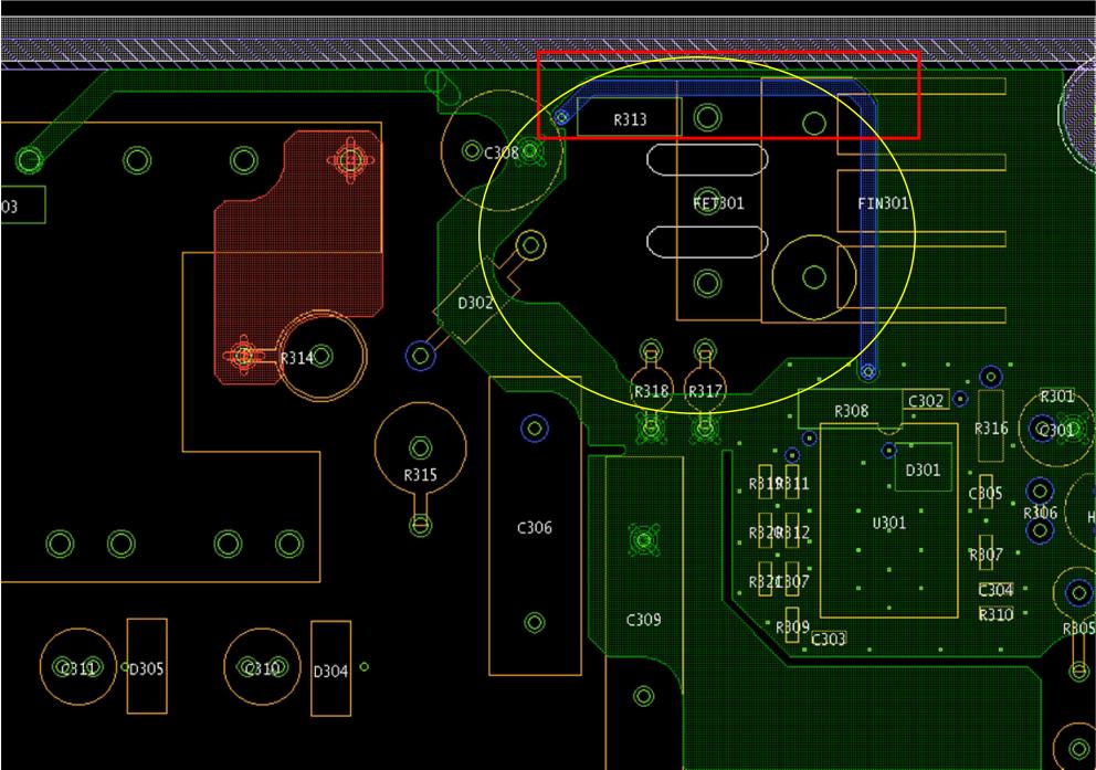
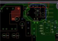
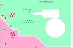
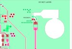
This is part of the flyback converter circuit. As you can see, the blue trace is the path connected to the gate of the FET through R313 to send fast PWM control signals to the FET. I have added GND (green) path at the upper part of the blue trace, highlighted in red rectangle to act as the nearest return for the PWM signal in order to minimize the current loop. But I have also created another ground loop, highlighted in yellow circle which I do not know whether there is any impact to the circuit (loop antenna effect?)

Please advice on this layout.


Closing the ground loop reduces the series inductance of the gate trace and is most likely advantageous.
 
My View, I would appreciate yours FvM as well please.
Ground Loops require different potentials to exist between different 'grounds' before a current will flow. They are mainly found when you are interconnecting seperate boards or seperate components, such as an Amp and a CD player in an audio system. On a PCB providing you use good ground layout practices, contigous planes are best, then you are not going to get ground loops. You would have to have some pretty high dI/dt and skinny tracks to create athe situation where a ground loop could occur. And as FvM has said reducing the ground series inductance, and thus will limit the effect of dI/dt. So I would concentrate on getting the lowest possible ground impedance, and keep it simple.
 
Thanks to FvM and Marce, helpful as always...

To elaborate more, the large GND plane at the lower part is the high current switching return path.
As you can see the GND path which is trying to contain the blue trace at the upper part of the board is made up of a thin trace only, which I doubt it's usefulness to the fast switching signal to the gate.

Besides, will the loop-like GND highlighted in yellow circle contributes to a loop antenna. FYI, it's in the inner layer of the board.
 

Looks about same size as a 4GHz remote arieal I did a few months back!!!!:evil:
I dont think it will have any effect, depends on so many factors, circuitry connected to it etc, but myself I wouldn't worry to much about such a feature.
I t would be interesting to get some views from an RF guy or two though.
 

If you fear loop inductance in some place, use a massive plane instead. I don't think, that referring to a loop antenna point of view is of much use in SMPS design, although electromagnetic theory apllies, of course.

The main area of interest should go to the commutating current loop, e.g. input capacitor, high-side and low-side switch (respectively diode) in a buck converter. Keep it's area as small as possible, use a (local) plane for it, if applicable. Then avoid spreading of the switched current into other parts of the design. Finally, aplly appropriate filtering to in- and output of the switcher.
 

So ground splitting is important for this case.
Yes I have done the high and low side separation and minimize this loop as much as possible to reduce magnetic field.

The question is the flow of the common return path, which goes first? Switching return goes back first to the source or the control part?
My opinion is control circuit return path comes after switching part to avoid contamination of the reference for the control circuit.
 

No splitting of ground planes Nelsonys,:shock: tut tut, that be a serious crime, It sound like there are two grounds, I prefer the term 'Creative Segmentation':grin:
On a serious note, i very rarely split my ground plane (like v=never), though with some switchers I do clear the ground, power and all signals from under the switching nodes to avoid capacitive pick up of the high frequency noise, as reccomended by some very nice people at Nation Semi. Anyway went to my SMPS folder and got a few interseting (hopefully) links. The EMC compliance club links should be on interest in this case as they focus on the EMC issues of laying out SMPS type circuits.

Excellent articles on EMC issues of SMPS design near the back.
http://www.compliance-club.com/pdf/Issue93.pdf
http://www.compliance-club.com/pdf/Issue94.pdf

An eclectic mix
**broken link removed**
http://www.fairchildsemi.com/an/AN/AN-6203.pdf
http://www.fairchildsemi.com/an/AN/AN-6858.pdf
http://www.fairchildsemi.com/an/AN/AN-42036.pdf
**broken link removed**
http://www.compliance-club.com/pdf/Issue93.pdf
http://www.compliance-club.com/pdf/Issue94.pdf

**broken link removed**
http://www.onsemi.com/pub_link/Collateral/AND8301-D.PDF

Keep on Routing.:wink:
 
Last edited:
  • Like
Reactions: FvM

    FvM

    Points: 2
    Helpful Answer Positive Rating
So ground splitting is important for this case.
With suggesting local ground planes, I didn't want to opt for split planes. The local ground should be implemented in addition to a continuous ground plane. You'll find a similar concept in Fairchildsemi's AN-42036, linked above by Marce. The important point is to separate the AC current loop (see National AN-1229) from the global ground plane. In some cases, a copper pour on the top side may be sufficient to achieve this.
 
The attached files illustrate the points mentioned. The top layer ground plane ( green) provides the localised switching loop return, the vias linking this segmented ground area to the main contiguous ground plane. The vias also provide thermal relief for the controlling IC, this design is from a few years ago, these days I would use thermal vias directly under the controller and have them capped. Having done some thorough thermal investigations of some design recently, after the main FPGA's, micro's etc the on board SMPS controllers were the next hottest thing. (We'll leave thermal management for another day:))
The other main points illustrated are:
Under the main noisy switching node the ground and power copper has been cleared to minimise capacitive coupling of the high frequency harmonics.
The feedback components are away from the noisy part of the circuit, and the feedback is taken from a point away from the SMPS and the quite side of the output capacitor.
The input, output and switching node tracks are exactly the right size, and the signals are guided through the respective input and output capacitors. This again minimises the amount of coupling the supply will have with any other circuitry.
This design is an extreme example of a simple SMPS design, that was done in conjunction with National Semi to minimise EMC issues with having multiple cascaded SMPS's on some boards, I now use it as a standard guideline for all our SMPS designs.
I also did a few large SMPS designs (200W upwards), which were fun, but I can't find the documentation at the moment, but the principles were the same just on a larger scale.
 

Attachments

  • PSU-Top-Layer.jpg
    PSU-Top-Layer.jpg
    149 KB · Views: 84
  • PSU-Ground-Layer.jpg
    PSU-Ground-Layer.jpg
    67.3 KB · Views: 120
  • PSU-Power-Layer.jpg
    PSU-Power-Layer.jpg
    82.7 KB · Views: 126
  • PSU-Bottom-Layer.jpg
    PSU-Bottom-Layer.jpg
    135.9 KB · Views: 114
Most noise that I usually pick up from the flyback converters I have designed is the dI/dt from the transformer used. Make sure your core is gaped so that you increase the inductance of the core to a few nH. I never had issues with creating a bigger/smaller trace for noise issues; most of the issues come from me doing a shitty job of winding my own transformer, or not gaping the core to the right inductance value. You will also get more noise since you are just using an external FET rather then a chip( one good company is www.powint.com) that has heat sensors and current limiting digital devices all in one package for further protection and less noise. Hipe that helps.

---------- Post added at 09:50 ---------- Previous post was at 09:49 ----------

Welcome To Power Integrations | Power Integrations
 

  • Like
Reactions: marce

    marce

    Points: 2
    Helpful Answer Positive Rating
Thanks Marce for those links, phewww.... I finally finished them today!

This is two-sided components PCB. If I wanna make it to single-sided components, where should I place these feedback resistors?
Do you think it is necessary to make the local plane connected with vias, coming out from the output capacitor larger? Say a plane which can fit in at least 6 vias?
Is it necessary to fit the plane connecting the capacitors exactly the same with their pad size, in decoupling speaking?
 

In addition, what is the practise for good bypassing? The local ground vias, I thought would it be better to place them outside the capacitors, instead of next to the IC.
 

Status
Not open for further replies.

Part and Inventory Search

Welcome to EDABoard.com

Sponsor

Back
Top