Continue to Site

Welcome to EDAboard.com

Welcome to our site! EDAboard.com is an international Electronics Discussion Forum focused on EDA software, circuits, schematics, books, theory, papers, asic, pld, 8051, DSP, Network, RF, Analog Design, PCB, Service Manuals... and a whole lot more! To participate you need to register. Registration is free. Click here to register now.

[SOLVED] 5V to 3.6 volt converion

Status
Not open for further replies.

dim912

Junior Member level 2
Joined
Sep 9, 2009
Messages
23
Helped
0
Reputation
0
Reaction score
0
Trophy points
1,281
Location
Colombo
Activity points
1,524
Hi all,

I am using PIC18F25J10 and it tolerable maximum
input voltage for RB0 and RB1 is 3.6V according
to its data sheet.

I am going to use this two pins to get external interrupts.
But the interrupt source device out put is 5V.
How can I interface this device with RB0 and RB1.

thank you..
 

A voltage divider using two resistors would work fine, for example 2k+3K

Alex
 
  • Like
Reactions: dim912

    dim912

    Points: 2
    Helpful Answer Positive Rating
Hi, you can make use of a 3.3V zener with a series resistor of approx 470E.

Marius
 
  • Like
Reactions: dim912

    dim912

    Points: 2
    Helpful Answer Positive Rating
or you can use a voltage regulator like lp5990. If you use the zener diode, don't forget to pay attention on reverse bias and specifications of diode. Just in case to use others power supply voltage.
 
  • Like
Reactions: dim912

    dim912

    Points: 2
    Helpful Answer Positive Rating
the interrupt source is a RFID reader. it uses W26 Wiegand 26 Bit Protocol(D0 and D1). therefore I need to work interrupts when those pins goes low. the bit rate is about 9600. so the voltage conversion mechanism should be faster enough.
today I tested this conversion using a LMopen loop opamp circuit.

+V =3.3 V
-V=GND.
Inverting input =3.3V
inverting input =0V.
non inverting input =5V interrupt source.
output = to RB1/INT1 pin of PIC 16f25j10

But it does not work as expected. the output voltage gives 1.5V even I connect the inverting input to GND.
So I am going to test using two diodes to drop 1.4V.

Thanks for your suggestions.
 

Why do you try complicated solution instead of a simple voltage divider?

Alex
 
  • Like
Reactions: dim912

    dim912

    Points: 2
    Helpful Answer Positive Rating
the interrupt source is a RFID reader. it uses W26 Wiegand 26 Bit Protocol(D0 and D1). therefore I need to work interrupts when those pins goes low. the bit rate is about 9600. so the voltage conversion mechanism should be faster enough.
today I tested this conversion using a LMopen loop opamp circuit.

+V =3.3 V
-V=GND.
Inverting input =3.3V
inverting input =0V.
non inverting input =5V interrupt source.
output = to RB1/INT1 pin of PIC 16f25j10

But it does not work as expected. the output voltage gives 1.5V even I connect the inverting input to GND.
So I am going to test using two diodes to drop 1.4V.

Thanks for your suggestions.

Suiggested diodes as you did not originally mention a high speed signal source.
Doubt they will work at that relative high speed, even a potential divider causes some waveform distortion.

You want to use a 74HC4050 - designed for just that job, have used it fine at much higher spi speeds.
 

Hi Alex,

I tried with the voltage divider. even the RF Reader output is labeled as 5V, its value when i connect any size of resister
is connected to it. But PIC inputs should be clear stable values. therefore i thought that using a open loop opamp is
more suitable.
I used two diodes to drop 1.4V. it works. but it is not reliable enough. even i touch pins of the diode, the interrupt works.
therefore i am not happy with it. And i am seeking for a more reliable way..

thanks all.
 

For the diodes to work properly a small current should flow in them when Vhi. So a resistor needs to be added between the interrupt pin and ground. Its value should be chosen based on the pin characteritics at both ends. The value 4K7 may be a good start
 
  • Like
Reactions: dim912

    dim912

    Points: 2
    Helpful Answer Positive Rating
dividers, zener diodes are just old fashion style to do bidirectional 5V to 3V ineterfacing.
The new way to do this is to use QuickSwitch buffers IDT - Integrated Device Technology - 5.0V QuickSwitch - they have specially designed MOSFET transistors which do this conversions without any problems. So you can do bidirectional 3V to 5V and back communications by simply placing one of the buffers between the lines. No delays, alsmost no loading. You can get up to 20 buffers inside single chip. Farnell can deliver the chip.
 
  • Like
Reactions: dim912

    dim912

    Points: 2
    Helpful Answer Positive Rating
Hi Alex,

I tried with the voltage divider. even the RF Reader output is labeled as 5V, its value when i connect any size of resister
is connected to it. But PIC inputs should be clear stable values. therefore i thought that using a open loop opamp is
more suitable.

I don't understand what you mean, why do you expect that the voltage divider output will not be stable?

Alternative ways are:

Bidirectional level translator
**broken link removed**

The 74AHC series (74AHC245) to interface the different voltages.
The AHC series can tolerate an input of 5v with a power supply of 3.3v so it can take 5v as input and output 3.3v
http://ics.nxp.com/products/ahc/datasheet/74ahc245.74ahct245.pdf

The 74LVC series can be also used, it can also tolerate a 5v input with 3.3 power supply.


dividers, zener diodes are just old fashion style to do bidirectional 5V to 3V ineterfacing.
The new way to do this is to use QuickSwitch buffers

So you wouldn't use an "old fashioned" way even if it works because there is a new way to do it?

Alex
 
  • Like
Reactions: dim912

    dim912

    Points: 2
    Helpful Answer Positive Rating
I don't understand what you mean, why do you expect that the voltage divider output will not be stable?
Alex

to Alex:
I am very sorry about my typing mistake. I meant that,

The typical output value of the RFID reader is mentioned as 5V. But when I use the voltage divider, this voltage drops. Therefore the voltage at the
Interrupt pin was not a stable and trusted value. It is better if I can have a stable and a precise voltage at the interrupt pin(RB1/INT1) since the
frequency of interrupts will be a higher value as the RFID reader gives its output at 9600bps.

I was not able to find 74AHC245 in the market. I was able to find HD74LS245P, but its minimum Vcc is mentioned as 4.75. so it will not be suitable.
At this moment i am trying with the LM393N comparator.

Thank all.
 

to Alex:The typical output value of the RFID reader is mentioned as 5V. But when I use the voltage divider, this voltage drops. Therefore the voltage at the Interrupt pin was not a stable and trusted value.

It seems strange that the output can't drive a 5K resistor (assuming that you have used 2K+3K), the current for that resistor is just 5v/5k=1mA.
You can use higher resistor values, for example try with 10K+20K, the current would be 5v/30K=160uA and the output (5*20K)/30K=3.33v

Alex
 
  • Like
Reactions: dim912

    dim912

    Points: 2
    Helpful Answer Positive Rating
When you say voltage drops, do you mean that the voltage of the power supply drops or the voltage at the output of the voltage divider? If the output of the RFID reader decreases, try decreasing current by using larger value resistors. What are the values of the resistors that you used for the voltage divider? You could also use very high value resistors and then use a buffer.

Hope this helps.
Tahmid.
 
  • Like
Reactions: dim912

    dim912

    Points: 2
    Helpful Answer Positive Rating
Just use a 5V tolerant logic gate for the interface. LCX logic is one family that works. I think there are others. You can buy just a single gate in a SOT23. Some of the recommendations on the rocketnumbernine site that was linked to are rather dubious.

Keith
 
  • Like
Reactions: dim912

    dim912

    Points: 2
    Helpful Answer Positive Rating
Thank you very much for all of your comments. Now my circuit is working safely.
They help me a lot and I learnt a lot form them.

finally I used a voltage devider(10K variable resister)
and a voltage follower(a simple opam) Op-amp Varieties .
The voltage divider(variable resistor) is adjusted to have 3.3V at it s middle leg and, it is connected to Vin of the voltage follower.
for voltage followers Vout=Vin . But a larger current can be drawn from the output side. therefor the voltage at the signal source(here RFID reader) does not
drop.


Thanks again..
 

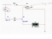
Hey .. i made a simple 5v - 3.6 volt(which is adjustable 0-5v) circuit. . saw your last thread after completing it!!! :lol:
That u made your circuit worked !!!
ok here is my circuit ---->

keep going .. :cool:
 
  • Like
Reactions: dim912

    dim912

    Points: 2
    Helpful Answer Positive Rating
Status
Not open for further replies.

Similar threads

Part and Inventory Search

Welcome to EDABoard.com

Sponsor

Back
Top