Continue to Site

Welcome to EDAboard.com

Welcome to our site! EDAboard.com is an international Electronics Discussion Forum focused on EDA software, circuits, schematics, books, theory, papers, asic, pld, 8051, DSP, Network, RF, Analog Design, PCB, Service Manuals... and a whole lot more! To participate you need to register. Registration is free. Click here to register now.

Problems with external interrupt (PIC18F4550)

Status
Not open for further replies.

jaco1982

Newbie level 4
Joined
Oct 4, 2010
Messages
7
Helped
0
Reputation
0
Reaction score
0
Trophy points
1,281
Activity points
1,332
Problems with external interrupt (PIC18F4553)

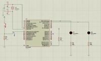
I'm having some issues getting an external interrupt (INT0) to work on a PIC18F4553. The code is written in MikroC, and I'm running a simulation in Proteus. When the external interrupt is triggered, nothing happens. Cam someone please see what I am missing?

Code:

Code:
void interrupt() {

     PORTC.F1 = 1;

}

void main() {

    TRISB = 0xFF;         // All port B pins are configured as inputs
    TRISC = 0x00;
    PORTC = 0x00;

    INTCON.GIE = 1;
    RCON.IPEN = 0;
    INTCON.INT0IE = 1;
    INTCON.INT0IF = 0;
    INTCON.PEIE = 1;
    INTCON2.INTEDG0 = 1;

    while(1){
       PORTC.B0 = 1;
    }
}

Schematic:
 
Last edited:

1) comment, comment and always comment on your code.
2) always set up your mcu correctly - use the right fuse settings.
3) always set up your port / pins correctly - read the datasheet.
4) if anything fails, read the datasheet and compiler manual again.

your issue comes from your lack of understanding of mcu's hardware and software requirement surrounding interrupts.
 
Its PIC18F4550 or PIC18F4553? Your proteus sim seems to have the 4453 version.
 

Are you able to just read the interrupt pin correctly ? (Sorry your .jpg wont expand to full size on my system so I cant see it properly)

I'm not familiar with proteus but simulators I've seen in the past cant do interrupts too well. Dont know about this one.

Also - on this chip does it take into account the LATB and LATC settings before it responds?

I'd echo the previous comments also

jack
 
My mistake. It is indeed a PIC18F4553 and not PIC18F4550.
 

Most people forget the simple first step of proving the hardware works correctly, pin settings are configured correctly in the microcontroller, you are reading from the correct pin, and reading the correct value.

The first thing you should do is write simple code that continously reads the pin and prints out the value as 1 or 0. If you push the button, and the number doesn't change, then one of the above things is incorrect.

If the above code loop doesn't reflect changes in the pushbutton, then interrupt code sure the heck won't work.

I don't know the PIC microcontroller, so you might need to clear your interrupt in the interrupt function?

Enlightenment
 
Last edited:
1) comment, comment and always comment on your code.
2) always set up your mcu correctly - use the right fuse settings.
3) always set up your port / pins correctly - read the datasheet.
4) if anything fails, read the datasheet and compiler manual again.

your issue comes from your lack of understanding of mcu's hardware and software requirement surrounding interrupts.

Most people forget the simple first step of proving the hardware works correctly and that you are reading from the correct pin.

Write simple code that continously reads the pin and prints out a 1 or 0. If you push the button, and the number doesn't change, then you have a hardware problem or you are reading the wrong pin.

If the above doesn't track the pushbutton, then interrupt code sure the heck won't work.

I don't know PIC, so you might need to clear your interrupt in the interrupt function?

Thank you for your comments gents. I tried to simply read the state of the pin, and discovered that it was not reading it correctly. I then went back to my textbook, and rered(sp?) the relevant chapter. I also played around a bit with the fuses, and it now works! I also managed to expand the system to incorporate a keypad through a MM74C922 keypad decoder - works like a charm.
Next step is to incorporate a LCD.
 

I am facing similar problem for pic18f4550 for external interrupt my source code is as below:

#include <p18F4550.h> // header file
#define mybit PORTBbits.RB7 //output pin
void chk_isr(void);
void INT0_ISR(void);
#pragma interrupt chk_isr
void chk_isr (void)
{
if (INTCONbits.INT0IF==1)
INT0_ISR( );
}
#pragma code My_HiPrio_Int=0x08

void My_HiPrio_Int (void)
{
_asm
GOTO chk_isr
_endasm
}
#pragma code
void main(void)
{
TRISBbits.TRISB7=0;
TRISBbits.TRISB0=1;
TRISC = 0xFF;
TRISD = 0;
INTCONbits.INT0IF=0;
INTCONbits.INT0IE=1;
INTCONbits.GIE=1;
while(1)
{
PORTD=PORTC;
}
}
void INT0_ISR(void)
{
mybit=~mybit;
INTCONbits.INT0IF=0;
}


i have tested this program in proteus but external interrupt is not working


Thanks in advance
 

Have you set RBIE bit in the INTCON flag - interrupt on change enable bit for port b

I do not use 'C', but can see no reference to it in the original post.

---------- Post added at 13:18 ---------- Previous post was at 13:15 ----------

any one please advice/help to solve this problem...

I can not see it referenced in your code either.
 
Thank you dhimullai for providing pic18f tutorial its realy usefull for me
 

Status
Not open for further replies.

Similar threads

Part and Inventory Search

Welcome to EDABoard.com

Sponsor

Back
Top