Continue to Site

Welcome to EDAboard.com

Welcome to our site! EDAboard.com is an international Electronics Discussion Forum focused on EDA software, circuits, schematics, books, theory, papers, asic, pld, 8051, DSP, Network, RF, Analog Design, PCB, Service Manuals... and a whole lot more! To participate you need to register. Registration is free. Click here to register now.

Inductance of sepic inductor winding.

Status
Not open for further replies.

eem2am

Banned
Joined
Jun 22, 2008
Messages
1,179
Helped
37
Reputation
74
Reaction score
24
Trophy points
1,318
Activity points
0
hello,

supposing one winding of this sepic inductor is open , and then the inductance of the other winding is measured....would the inductance read 100uH?

Sepic inductor = MSD7342-104ML (100uH)

** Sepic inductor datasheet =
https://www.coilcraft.com/pdfs/msd7342.pdf

if both windings are in series, then would the inductance of the two in series read 400uH?
(assuming the windings are connected dot to no_dot)

If both windings are paralleled, would the inductance read 100uH?
(assuming they are paralleled with dot connected to dot)
 

All three answers yes, assuming a perfect coupling of both windings (k=1).
 
  • Like
Reactions: eem2am

    eem2am

    Points: 2
    Helpful Answer Positive Rating
Yaa i am agree with FvM
 
  • Like
Reactions: eem2am

    eem2am

    Points: 2
    Helpful Answer Positive Rating
the thing is,

when in use , the SEPIC with a coupled 1:1 sepic inductor of 100uH (100uH = each coil with other open) behaves like a circuit with two uncoupled inductors of value 200uH.

.. presumably , this is because, the current induced in the opposite "coil" (i.e. the other coil to the one that we are considereing current flow in) creates a field component with the same direction as the coil in which current flow is being considered?


so you agree that a 100uH coupled inductor sepic circuit behaves like a sepic with two uncoupled 200uH inductors?
 
In the notes from your data sheet on page 2 it says,

2. Inductance shown for each winding, measured at 100 kHz, 0.1 Vrms, 0 Adc on an Agilent/HP 4284A LCR meter or equivalent. When leads are connected in parallel, inductance is the same value. When leads are connected in series, inductance is four times the value.

You would expect this because L = Al.N^2, where Al is the specific inductance per root turn. So you double the number of turns you get four times the inductance.

I don't think you will find that the coupled 100uH inductor behaves or rather performs in the same way as two separate 200uH inductors. Looking at the data sheet circuit for SEPIC,

**broken link removed**

In DC terms C1 must charge to VIN. With Q1 on then VIN is placed across L1 and also the same voltage is forced across L2 by C1, given it is charged to VIN. Visually it looks like L2 has -VIN across it but the 'dots' are such that effectively the pair of inductors are being driven with the 'same' voltage in parallel.

You do not want 100% coupling in this application since it would force currents in the inductors to be discontinuous saw tooths. It is the leakage inductance that prevents this from happening and also allows you to take advantage of 'ripple current steering'.

1980 - 2003 Unitrode Design Seminars
**broken link removed**

SLUP103
SLUP104
SLUP105

Of course the devices you are looking at will not be for 200W PFC applications but the principles remain the same. If you do wish to implement ripple current steering then as per the above papers given the SEPIC output is noisy anyway you would wish to steer ripple current into L2 which means the leakage inductance would be placed in series with L1.

Depending on how the devices you are looking at are manufactured then that leakage might be equally distributed. Otherwise you might wish to measure each winding with the other shorted to determine where it is located. The short circuited winding with the highest measured inductance referenced to the other would be the one to place at the input in your design.

Having determined what that 'leakage' inductance is you will be able to work out what sort of damping is required across C1.

Genome
 
  • Like
Reactions: eem2am

    eem2am

    Points: 2
    Helpful Answer Positive Rating
that leakage might be equally distributed
It's supposed by operation principle of coupled incuctors. You don't have more parameters available than L1, L2 and k. So if L1 and L2 are equal, the mutual inductances must be, too.

Rs will be most likely different, and can be a reason for a particular windings assingment.

P.S.: I found, that apparently no vendor feels a need to specify a coupling factor for his SEPIC inductors, although e.g. Wuerth (we-online.com) even distinguishes between "low" leakage inductance types for flyback and "high" for SEPIC. So you have to measure it yourself. Measuring both individual windings and a series circuit of both is the easiest way to get the parameters with standard equipment, I think. With a four-wire LCR meter, you can measure Lmut directly.
 
Last edited:
  • Like
Reactions: eem2am

    eem2am

    Points: 2
    Helpful Answer Positive Rating
Hi FvM

If you read SLUP105 from the previous link,

**broken link removed**

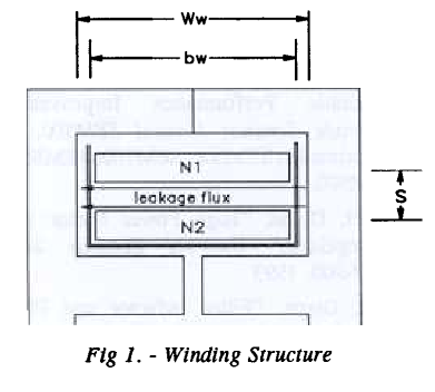
72_1295542280.png


Then you will see that the leakage flux, from which leakage inductance arises, has been designed to be associated with N1. It exists in the gap between the two windings and is not coupled with N2. If you were to take a device constructed in this manner and make short circuit tests of inductance you would find that the leakage inductance N1 to N2 is greater than N2 to N1.

Genome
 
  • Like
Reactions: eem2am

    eem2am

    Points: 2
    Helpful Answer Positive Rating
I think, the strange result (in my opinion) is brought on by assuming that the individual inductances are equal. But they aren't - due to the asymmetric design. So you get different inductances, when measuring either L1 or L2, and another, different value for the parallel circuit. But if you prefer the asymmetric equivalent circuit from SLUP105, than you get different leak inductances - according to the definition. In the standard transformer equivalent circuit, you have L1, L2 and a coupling factor k. It's the equivalent circuit, that's e.g. used in SPICE simulators.
 
  • Like
Reactions: eem2am

    eem2am

    Points: 2
    Helpful Answer Positive Rating
I would not wish to disagree. The subject is more complex than my understanding.

Conceptually inductors and magnetics are hard and I would not doubt that in the given picture individual measured values for L1/N1 and L2/N2 would differ. I do not think you would be able to attribute that difference to leakage inductance or its location. It is the 'uncoupled energy' that exists in the space between the windings. It is similar to the case of a gapped inductor. The energy is stored in the gap.

I would not be certain but I do not think Spice handles complex magnetic structures such as multi-winding transformers with differing coupling factors between the windings very well, if at all. Usually it just gives up and moans at you suggesting that the the circuit is unrealisable or something similar. It's not that it can't exist in real life it's just that it hurts Spice's head. Perhaps the telling thing would be that if you write,

K1 L1 L2 0.95
K2 L2 L1 0.90

In the expectation that you might be able to implement a circuit that models the relative coupling L1 to L2 and L2 to L1 Spice will tell you that you have already defined a value or that you have made multiple definitions. Otherwise if you try and create a multiple winding structure and attempt to define multiple and differing coupling coefficients between the windings as suggested Spice will just fall over. There are descriptions somewhere about what would be required in terms of definitions to keep the underlying 'engine' happy but it is much simpler to make K One/1 for everything and then add discrete leakage inductances in series with the appropriate windings.

This might be me using the 'tool' incorrectly but I have never been able to get a multi-winding transformer with differing K between windings past pre-processing so I always set K to One for All and add the parasitics as I see fit.

Genome

Edit

No, in fact that did not work either. I, and others, have had to set up discrete sub-circuits of the blocks involved in the construction of magnetic components in order to more realistically model under Spice how the actual device does perform.

I think I shall exit stage left on this one because I may not have the required testosterone levels..
 
Last edited:
  • Like
Reactions: eem2am

    eem2am

    Points: 2
    Helpful Answer Positive Rating
According to network theory, three parameters are sufficient to describe a reciprocal two-port. In so far the PSPICE model is complete. But it's not referring to real components of an equivalent circuit, while the model from the Unitrode/TI paper wants to be visual. In any case, you should be able to convert one model description into the other.
 
  • Like
Reactions: eem2am

    eem2am

    Points: 2
    Helpful Answer Positive Rating
Status
Not open for further replies.

Part and Inventory Search

Welcome to EDABoard.com

Sponsor

Back
Top